Electric appliance device and electric connection device thereof

A technology for electrical connection devices and electrical devices, which is applied in the direction of two-part connection devices, parts and connections of connection devices, and can solve problems such as inability to solve the contradiction between assembly and use performance, failure to obtain use performance, and large operating force of the drive device. , to achieve the effect of reducing size, reducing temperature rise and ensuring contact stability

Pending Publication Date: 2020-07-10
SHANGHAI LEADING CONNECTION MECHATRONICS TECH CO LTD +1
View PDF0 Cites 12 Cited by
  • Summary
  • Abstract
  • Description
  • Claims
  • Application Information

AI Technical Summary

Problems solved by technology

A three-pole circuit breaker has at least six electrical connection devices, including three incoming electrical connection devices and three outgoing electrical connection devices, so increasing the clamping force will double the resistance of the main body busbar inserted into the contact bridge, and eventually cause the main body It is difficult to insert the busbar into the electrical connection device, and the operating force of the drive device of the entire drawer device will be unacceptably large
[0006] In summary, the electrical connection devices used in the prior art have the following defects: there is an obvious contradiction between the difficulty of assembly and the performance
[0007] The structure of the electrical connection device in the prior art makes it impossible to solve the contradiction between assembly and performance, and only a compromise solution can be obtained between the two
But the compromise solution can not get the best performance

Method used


Image

  • Electric appliance device and electric connection device thereof
  • Electric appliance device and electric connection device thereof
  • Electric appliance device and electric connection device thereof

Examples


Embodiment Construction

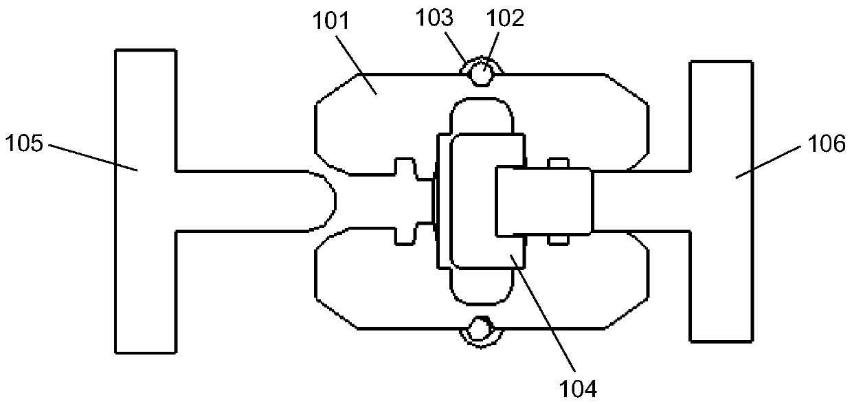
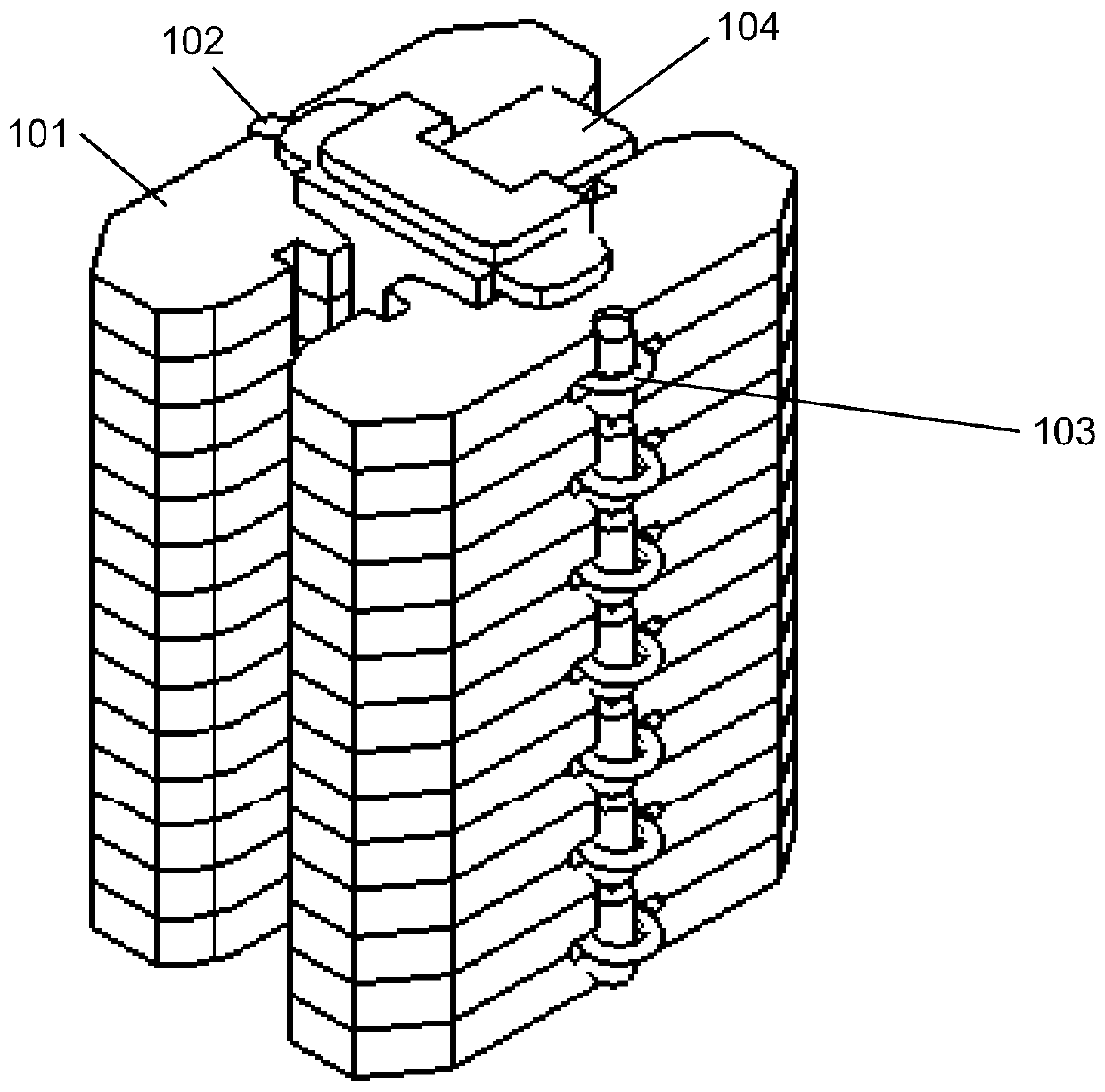
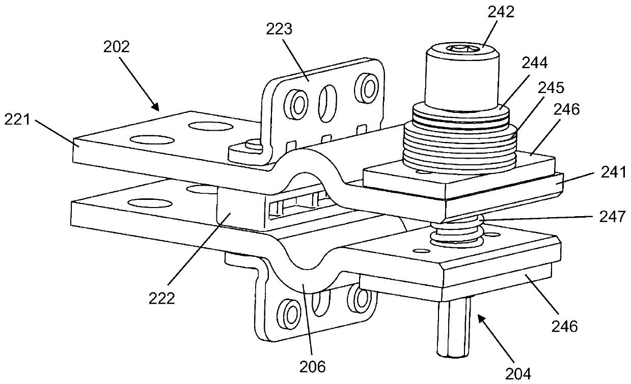
[0035] The present invention proposes an electrical connection device that separates the inserting and clamping operations, and can fit the busbar of the body as much as possible to increase the contact area. Figure 2a with Figure 2b A structural diagram of an electrical connection device according to a first embodiment of the present invention is disclosed, wherein Figure 2a is a three-dimensional structure diagram of the electrical connection device, Figure 2b It is a side structural view of the electrical connection device. As shown in the figure, the electrical connection device includes: a withdrawable device connection component 202 , a body connection component 204 and a flexible component 206 . The withdrawable device connection assembly 202 is fixed on the withdrawable device and is electrically connected to the incoming and outgoing wire ends of the withdrawable device. The body connection assembly 204 includes a contact piece with a clamping mechanism, which ...


PUM


Abstract

The invention discloses an electric connection device, and the deviceis connected between a body of an electric appliance device with a draw-out structure and a draw-out device. The device comprises adraw-out device connection assembly, a body connection assembly and a flexible assembly. The draw-out device connection assembly is fixed on the draw-out device and is electrically connected with thewire inlet and outlet ends of the draw-out device. The body connection assembly comprises a contact piece with a clamping mechanism, and the clamping mechanism enables the contact piece to be tightlyattached to and clamp the body busbar. The flexible assembly is connected with the draw-out device connection assembly and the body connection assembly, and the body connection assembly, the flexibleassembly and the draw-out device connection assembly form a conductive path. The contact pieces of the body connection assembly are adapted to the position deviation of the body busbar to generate deviation, so the contact pieces are tightly attached to and clamp the body busbar, and the flexible assembly absorbs the deviation of the contact pieces through self deformation, so the deviation is not transmitted to the draw-out device connecting assembly.

Description

technical field [0001] The invention relates to the field of medium and low-voltage electrical appliances, and more specifically, relates to an electrical connection component in an electrical device with a withdrawable structure. Background technique [0002] Electrical devices with withdrawable structure include: universal circuit breaker, molded case circuit breaker, automatic transfer switch with drawer device, medium voltage circuit breaker, medium voltage switchgear, etc. A device with a withdrawable structure includes a body and a withdrawable device. The main body uses bridge-type contacts as the main body busbar, and the draw-out device is provided with a contact bridge for electrical connection with the main body busbar. The contact bridge on the withdrawable device is connected with the external incoming and outgoing wire ends. When the main body is pushed into the withdrawable device, the bus bar of the main body contacts with the contact bridge to form a condu...

Claims


Application Information

Patent Timeline
Patent Type & Authority Applications(China)
IPC IPC(8): H01R13/04H01R13/10H01R13/621H01R13/631H01R13/639H01R24/00
CPCH01R13/621H01R13/639H01R13/6315H01R13/04H01R13/10H01R24/005H01H71/08H01H71/10H02B11/12H01R4/40H01R4/42H02B11/04H01H1/365H01H1/50
Inventor 施政
Owner SHANGHAI LEADING CONNECTION MECHATRONICS TECH CO LTD
Why Eureka
Try Eureka