Current limiting method of transformer current limiting device based on manual zero-crossing current limiting

A current limiting method and technology of a current limiting device, applied in the field of transformers, can solve the problems of complex structure, increased operating loss, large operating loss, etc., and achieve the effects of improving economic benefits, improving current limiting effect, and increasing operating loss

Active Publication Date: 2020-08-21
天津动态智能科技有限公司 +3
View PDF6 Cites 3 Cited by
  • Summary
  • Abstract
  • Description
  • Claims
  • Application Information

AI Technical Summary

Problems solved by technology

However, due to the cumulative effect of short circuit, the short circuit strength of the winding will decrease after being subjected to multiple short circuit current impacts, so short circuit faults may still occur
The second is to limit the short-circuit current by increasing the short-circuit impedance or connecting an external current-limiting reactor. This method has a large operating loss and will cause the bus voltage to fluctuate with the load, which will cause power quality problems and limit the operation of the power grid.
When the resonant current limiter is in normal operation, the capacitance and inductance elements pass through, so the loss is relatively large. The arc transfer current limiter relies on the rapid identification of short-circuit faults and manual zero-crossing technology. The structure is complex and the reliability is not high. The fast switching current limiter Limiting the current after the short-circuit current naturally crosses zero, the first peak value of the short-circuit current cannot be limited, and the current limiting effect is poor, and all fault current limiters, like current-limiting reactors, require a larger installation location in actual use and occupy an area in the substation As the area becomes smaller and the structure design becomes more and more compact, the limiter is therefore more and more restricted.
In summary, when the installation area is limited by size, there is an urgent need for a current-limiting device that is small in size, easy to install and maintain, does not increase operating losses, and has a good current limiting effect. At present, there is no limit to the short-circuit current of transformers. Economical and reliable technical measures

Method used


Image

  • Current limiting method of transformer current limiting device based on manual zero-crossing current limiting
  • Current limiting method of transformer current limiting device based on manual zero-crossing current limiting

Examples


Embodiment Construction

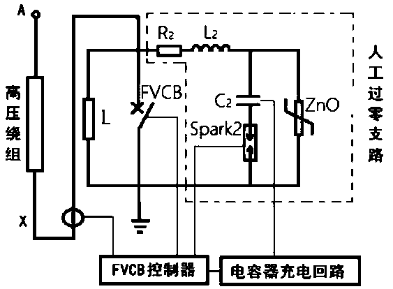
[0027] The following will refer to the attached Figure 1 to Figure 2 Specific examples of the present invention are described in more detail. Although specific embodiments of the invention are shown in the drawings, it should be understood that the invention may be embodied in various forms and is not limited to the embodiments set forth herein. Rather, these embodiments are provided for more thorough understanding of the present invention and to fully convey the scope of the present invention to those skilled in the art.

[0028] It should be noted that certain terms are used in the specification and claims to refer to specific components. Those skilled in the art should understand that they may use different terms to refer to the same component. The specification and claims do not use differences in nouns as a way of distinguishing components, but use differences in functions of components as a criterion for distinguishing. "Includes" or "comprises" mentioned throughout ...


PUM


Abstract

The invention discloses a current limiting method of a transformer current limiting device based on manual zero-crossing current limiting. When a short circuit fault occurs, a controller immediately sends a switching-off instruction to a rapid vacuum circuit breaker after judging the short-circuit fault; when the rapid vacuum circuit breaker is switched off and the distance between contacts reaches a rated opening distance, the controller switches on a controllable discharge gap Spark2; a capacitor C2 and an inductor L2 are connected in series for resonance so as to generate reverse high-frequency current equivalent to the instantaneous amplitude of the short-circuit current and superpose the reverse high-frequency current on a rapid vacuum circuit breaker loop; the quick vacuum circuit breaker completes short-circuit current switching-on and switching-off; then, the short-circuit current is transferred to a ZnO branch of a zinc oxide arrester and the capacitor C2 is charged; when thevoltage of the capacitor C2 tends to be stable and reaches the residual voltage of the zinc oxide arrester ZnO, the zinc oxide arrester ZnO is switched on, the controllable discharge gap Spark2 is switched off, then the zinc oxide arrester ZnO continuously absorbs short-circuit current energy, and the zinc oxide arrester ZnO is switched off when the current crosses zero.

Description

technical field [0001] The invention relates to the field of transformers, in particular to a current limiting method of a transformer current limiting device based on artificial zero-crossing current limiting. Background technique [0002] The transformer is the hub of the grid to transmit electric energy and the main equipment of the grid operation. The transformer is a device that uses the principle of electromagnetic induction to change the AC voltage. The winding of the power transformer is short-circuited, especially when the load is short-circuited. If the damage is great, it will affect the normal use of the transformer, and even affect the entire power transmission system in severe cases. [0003] In the current transformer structure, in order to avoid the harm caused by the short circuit of the transformer, one of the measures taken is to improve the short circuit strength of the transformer in the design and manufacturing process, such as maintaining the ampere-tu...

Claims


Application Information

Patent Timeline
Patent Type & Authority Applications(China)
IPC IPC(8): H02H9/02H01F27/34
CPCH01F27/34H02H9/02
Inventor 马奎王曙鸿
Owner 天津动态智能科技有限公司
Why Eureka
Try Eureka