Cutting structure for V-belt cutting machine and V-belt cutting machine

A V-belt and cutting machine technology, which is applied in metal processing and other directions, can solve the problems of unqualified dimensions of the V-belt blank layer, achieve the effects of improving pre-cutting accuracy, improving surface smoothness, and avoiding lateral misalignment

Active Publication Date: 2021-12-07
大畏机床(江苏)有限公司
View PDF9 Cites 0 Cited by
  • Summary
  • Abstract
  • Description
  • Claims
  • Application Information

AI Technical Summary

Problems solved by technology

[0005] Aiming at the deficiencies of the prior art, the present invention discloses a cutting structure for a V-belt cutting machine and a V-belt cutting machine, which can solve the problem that the size of the cut V-belt blank layer is unqualified due to misalignment between the processing layer and the cutting knife

Method used


Image

  • Cutting structure for V-belt cutting machine and V-belt cutting machine
  • Cutting structure for V-belt cutting machine and V-belt cutting machine
  • Cutting structure for V-belt cutting machine and V-belt cutting machine

Examples


Embodiment 1

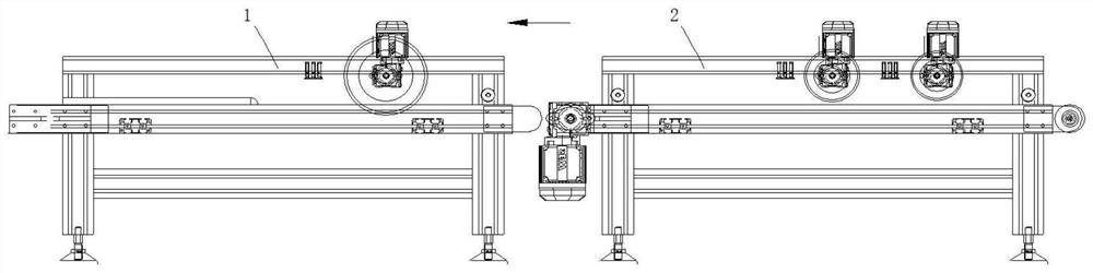
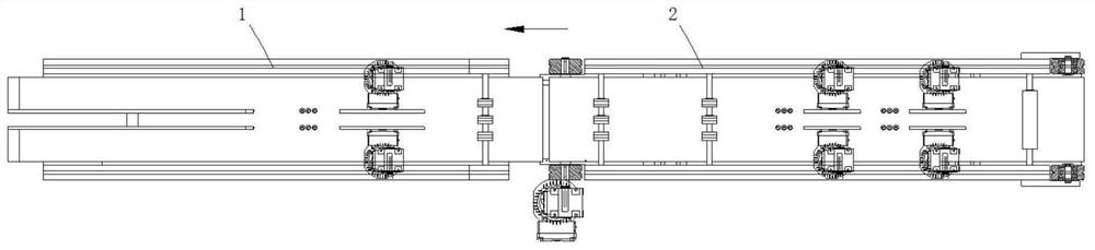
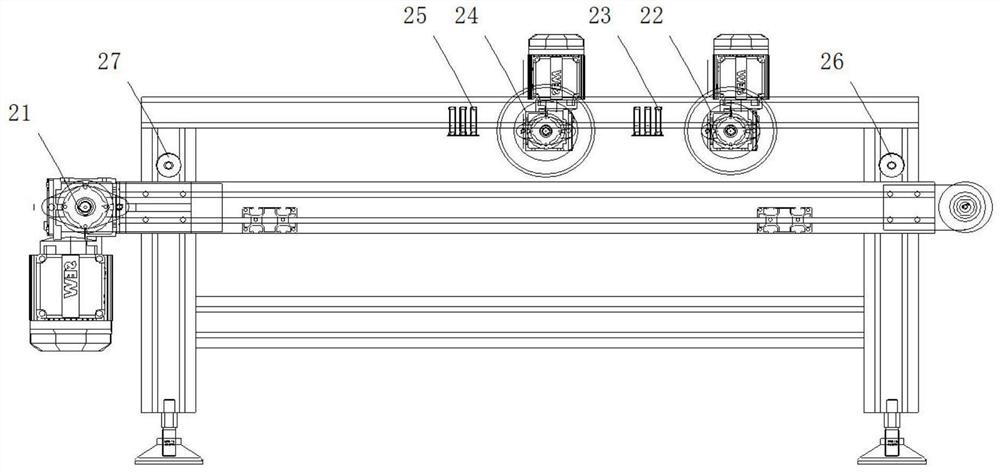
[0058] Such as Figure 1 to Figure 10 As shown, the cutting structure for the V-belt cutting machine described in the embodiment of the present invention includes a cutting frame 1 for cutting the V-belt into strips, a pre-cutting frame 2 for cutting a part of the upper surface of the V-belt, Along the delivery direction (shown in the direction of the arrow) of the V-belt cutting machine, the tail end of the pre-cutting frame 2 is connected with the head end of the cutting frame 1, and the pre-cutting frame 2 includes

[0059] The first conveyor 21 is used to transport the V-belt to be cut, and the first conveyor 21 extends along the conveying direction of the V-belt cutting machine;

[0060] At least one pressing wheel 22 is driven by a motor, and is used to form a pre-cut recess extending along the conveying direction of the V-belt cutting machine on the upper surface of the V-belt to be cut, and the pressing wheel 22 and the first conveying The conveyor 21 is rotatably con...

Embodiment 2

[0088] Such as Figure 11 to Figure 15 As shown, the present invention also discloses a V-belt cutting machine, including a cutting structure for a V-belt cutting machine and a material guide frame 3, and the cutting structure for a V-belt cutting machine is for the V-belt cutting machine described in Embodiment 1. Cutting structure, the V-belt cutting machine connects the tail end of the material guide frame 3 with the head end of the cutting structure.

[0089] In order to guide the V-belt to be cut, the material guide frame 3 includes at least one second positioning roller 31, the second positioning roller 31 is rotationally connected with the material guide frame 3, and the second positioning roller 31 Relative to the upper surface of the material guide frame 3, the upper surface is suspended, the axial extension of the second positioning roller 31 extends in the horizontal direction, and the axial direction of the second positioning roller 31 is vertical to the conveying ...

Embodiment 3

[0091] Such as Figure 16 As shown, a plurality of the second positioning rollers 31 can also be provided, and the plurality of the second positioning rollers 31 are arranged at intervals along the extending direction of the material guide frame 3 .

[0092] Refer to Example 2 for other undescribed structures.

[0093] It should be noted that in this article, relational terms such as first and second are only used to distinguish one entity or operation from another entity or operation, and do not necessarily require or imply that there is a relationship between these entities or operations. There is no such actual relationship or order between them.


PUM


Abstract

The invention discloses a cutting structure for a V-belt cutting machine and a V-belt cutting machine. It includes a cutting frame for cutting the V-belt into strips, a pre-cutting frame for cutting a part of the upper surface of the V-belt, and along the conveying direction of the V-belt cutting machine, the tail of the pre-cutting frame The end is connected to the head end of the cutting frame, and a first conveyor, at least one pressure wheel, a first detection unit, at least one pre-cutting wheel, and a second detection unit. The invention can solve the problem that the size of the cut V-belt blank layer is unqualified due to misalignment between the processing layer and the cutting knife.

Description

technical field [0001] The invention relates to the technical field of a V-belt cutting machine, in particular to a cutting structure for a V-belt cutting machine and a V-belt cutting machine. Background technique [0002] There are two kinds of special belt core structure and rope core structure for the triangle belt, which are composed of four parts: covering cloth, top rubber, tensile body and bottom rubber. The V-belt with rope core structure is easy to manufacture, the tensile strength is average, the price is low, and it is widely used. The V-belt with special core structure has good toughness and high strength, and is suitable for occasions with high speed. When the V-belt is made into a tube, it needs to be cut into a strip-shaped rough V-belt structure, and then the subsequent trimming and grinding are carried out. The scraps and slag in the cutting tool are easy to contaminate on the cutting knife, affecting the work of the cutting knife, and the tension of the pr...

Claims


Application Information

Patent Timeline
Patent Type & Authority Patents(China)
IPC IPC(8): B26D11/00B26D7/02B26D7/06B26D7/00
CPCB26D7/00B26D7/025B26D7/06B26D11/00B26D2007/0012
Inventor 赖剑峰张金新
Owner 大畏机床(江苏)有限公司
Why Eureka
Try Eureka