A mixer feeding device for building construction

A technology for building construction and mixer, which is applied to clay preparation devices, mixing operation control devices, mixing operation control and other directions, can solve problems such as difficulty, troublesome operation, low efficiency, etc., and achieves improved cutting speed, simple structure, and difficulty in operation. low effect

Active Publication Date: 2021-08-06
新昌县品创建筑设计有限公司
View PDF0 Cites 0 Cited by
  • Summary
  • Abstract
  • Description
  • Claims
  • Application Information

AI Technical Summary

Problems solved by technology

[0003] However, when this kind of forced mixer is in use, workers directly put the materials piled on the ground into the concrete, and often mix large objects such as stones. When painting the wall or pouring the ground in the later stage, it is necessary to It is more cumbersome to clean up such objects, especially if there is a requirement for the particle size of the concrete, and it is necessary to screen out the coarse sand, which is difficult to operate manually
However, using a screening machine for screening and then cutting is inefficient.

Method used


Image

  • A mixer feeding device for building construction
  • A mixer feeding device for building construction
  • A mixer feeding device for building construction

Examples


Embodiment 1

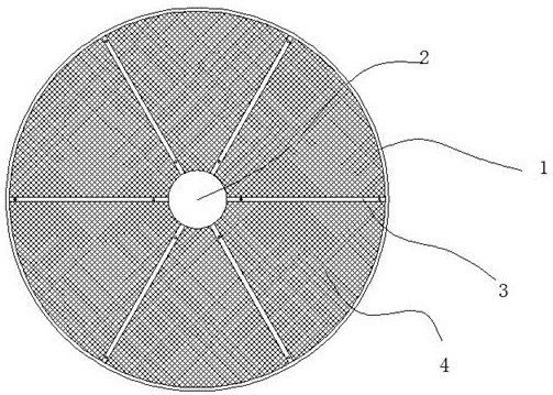
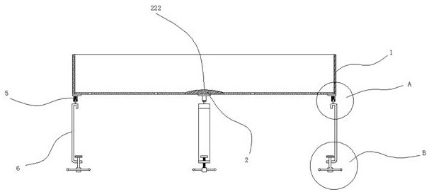
[0035]A mixer blanking device for building construction, comprising a container 1 arranged above the mixer, the diameter of the container 1 is not smaller than the diameter of the mixer, and an axis block 2 is arranged at the bottom axis of the container, the A plurality of connecting rods 3 are welded between the axis block 2 and the container 1, a fan-shaped area is formed between two adjacent connecting rods 3, and a metal screen 4 is welded in the formed fan-shaped area; A support structure 6 is installed at the side wall, and a quick-release structure 5 is fitted between the support structure 6 and the container 1; a scraper device 7 is installed at the position of the stirring shaft of the mixer, and the scraper device 7 follows the The rotation of the stirring shaft rotates, and the scraping device 7 acts on the metal screen 4 .

[0036] The depth of the container 1 is 20cm~30cm.

Embodiment 2

[0038] The top of the connecting rod 3 is processed into a ∧ shape, the top of the connecting rod 3 is vertically penetrated with a through hole 301, and a partition 302 is installed above the connecting rod 3, and the bottom of the partition 302 is arranged There is a ∧-shaped groove 303 corresponding to the connecting rod 3, and an insertion shaft 304 inserted into the through hole 301 is welded at the bottom of the partition 302, and the mesh sizes of the adjacent two metal screens 4 are different. . A blanking gap is formed between two adjacent partitions. When we are blanking, we start blanking through the edge of the container 1. The end of the partition away from the inner wall of the container 1 is disconnected, so when the blanking is insufficient, or the metal sieve When the screen is blocked and the material cannot be discharged in time, the excess raw material can leak from the gap between the ends of the adjacent partitions, and the material can be discharged from...

Embodiment 3

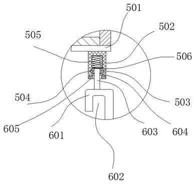
[0040] The quick-release structure 5 includes a steel plate 501 welded at the bottom of the container 1, and a sleeve 502 arranged at the bottom of the steel plate 501, and an annular groove 503 is provided on the inner wall of the sleeve 502. A rubber limit ring 504 is installed in the annular slot 503, a spring 505 is arranged inside the sleeve 502, and a slider 506 is arranged below the spring 505 inside the sleeve 502, the slider 506 The block 506 moves down and is limited by the rubber stop ring 504; the support structure 6 includes a rod 601, and the upper end of the rod 601 is bent to form a buckle groove 602. When installed, the mixer shell snapped into the buckle groove 602, an insertion shaft 603 is arranged on the top of the rod 601, the insertion shaft 603 is inserted into the sleeve 502, and the upper end of the insertion shaft 603 is against the slider 506, the insertion shaft 603 is provided with a retaining ring 604, the retaining ring 604 is located below the ...


PUM

PropertyMeasurementUnit
depthaaaaaaaaaa

Abstract

The invention discloses a mixer blanking device for building construction, which comprises a container arranged above the mixer, the diameter of the container is not smaller than the diameter of the mixer, and an axis block is arranged at the bottom axis of the container, so that A plurality of connecting rods are welded between the axis block and the container, a fan-shaped area is formed between two adjacent connecting rods, and a metal screen is welded in the formed fan-shaped area; There is a support structure, and there is a quick-release structure between the support structure and the container; this product can be assembled on the top of the mixer, and the raw materials are screened while discharging.

Description

technical field [0001] The invention relates to a mixer feeding device for building construction. Background technique [0002] Compulsory mixers have been rapidly developed and promoted since their rise in the early 1950s. What occur at first is that the disk vertical shaft type is forced concrete mixer. This kind of mixer is divided into turboprop type and planetary type. After the 1870s, with the application of light aggregates, a circular groove horizontal shaft forced mixer appeared, which is divided into two types: single horizontal shaft and double horizontal shaft, and has the characteristics of self-falling and forced mixing. . The linear speed of the stirring blade is small, the wear resistance is good and the energy consumption is small, and the development is fast. The shaft arm frame in the mixing barrel of the forced concrete mixer is equipped with stirring blades, and the materials added to the mixing barrel will form a cross flow under the strong agitatio...

Claims


Application Information

Patent Timeline
Patent Type & Authority Patents(China)
IPC IPC(8): B07B1/04B28C7/00
CPCB07B1/04B28C7/0007
Inventor 蔡汉阳熊元庆蔡月连
Owner 新昌县品创建筑设计有限公司
Why Eureka
Try Eureka