A dehumidifier for switchgear

A technology of switchgear and dehumidification box, which is applied in the cooling/ventilation of substation/switchgear, details of substation/switch layout, substation/power distribution device shell, etc., which can solve incomplete exhaust, air turbulence, and influence on air flow order and other issues to achieve the effect of avoiding potential safety hazards, ensuring orderly entry, and avoiding dust and static electricity

Active Publication Date: 2022-07-08
江山市鑫源电气有限公司
View PDF7 Cites 0 Cited by
  • Summary
  • Abstract
  • Description
  • Claims
  • Application Information

AI Technical Summary

Problems solved by technology

[0002] The switch cabinet is a kind of electrical equipment. The outside line of the switch cabinet first enters the main control switch in the cabinet, and then enters the sub-control switch. Each branch is set according to its needs, such as instruments, automatic control, motor magnetic switches, various AC contactors, etc. For some switch cabinets, if the moisture can dissipate in a short period of time, dehumidification is not necessary, but in rainy weather, condensation, water droplets, or even water will appear in the switch cabinet. Dehumidification is necessary, which seriously affects The performance of the internal insulation material and the stability of the switchgear operation
[0003] Since the equipment in the switchgear is in a relatively high temperature state when the equipment in the switchgear is working, the humidity in the air in the switchgear is mainly high. When the conventional switchgear is dehumidified, it mainly uses the fan exhaust method, such as China Patent Notification No. CN210273258U proposes a dehumidification device for switchgear with a heating device for rapid evaporation of water, but the problem is that the air turbulence that may be caused by the fan operation affects the order of air circulation, resulting in incomplete exhaust. And the direct entry of external air will affect the overall effect, and it will also cause safety problems such as dust and static electricity due to the rapid airflow driven by the fan

Method used


Image

  • A dehumidifier for switchgear
  • A dehumidifier for switchgear
  • A dehumidifier for switchgear

Examples


Embodiment 1

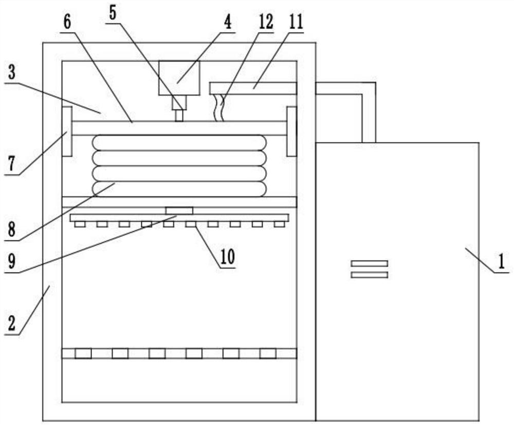
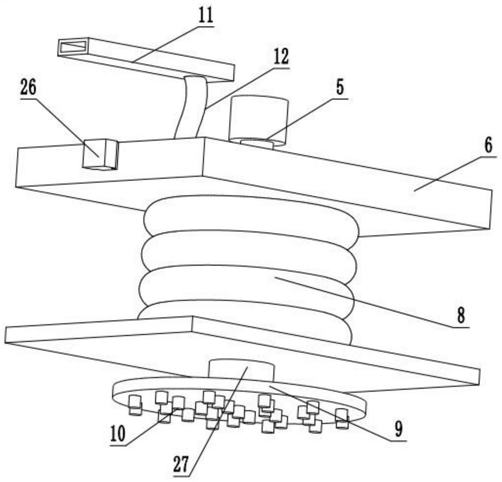
[0017] Example 1: see Figure 1-3 , a dehumidification device for a switch cabinet, comprising a dehumidification box 1 arranged side by side with the switch cabinet body 2, a one-way air flow device 3 connected to the dehumidification box 1 is arranged in the upper part of the switch cabinet, and a side lower part of the dehumidification box 1 is provided. There is a return air outlet 25 which is communicated with the inside of the switchgear body 2. During the dehumidification work of the switchgear, the air in the switchgear body 2 is drawn out in one direction through the one-way air flow device 3, and is dried in the dehumidification box 1. After that, it is sent back into the switch cabinet body 2 by the return air jet port 25, thereby avoiding the interference of the external air to the dehumidification process. The one-way air flow device 3 includes a hydraulic cylinder 4 and an expansion air bag 8. In the center of the inner top surface of the cabinet body 2, a liftin...

Embodiment 2

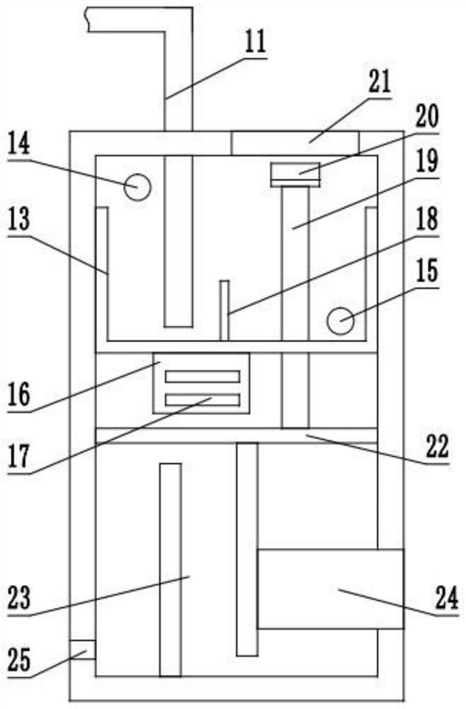
[0020] Example 2: On the basis of Example 1, a drawer box 24 that is slidably connected to the side of the dehumidification box 1 is inserted. The drawer box 24 is located in the rotary channel 23 and below the connecting vertical pipe 19, and the inside of the drawer box 24 is hollow. In addition, the upper and lower ends are open, and during dehumidification, a filter screen can be installed in the drawer box 24 to avoid incomplete cleaning of the dehumidification screen cover 20 .

[0021]The top of the dehumidification box 1 is provided with a cleaning window 21, which is located directly above the connecting vertical pipe 19. The cleaning window 21 is used to clean and replace the dehumidification net cover 20 in time to ensure the dehumidification effect.

Embodiment 3

[0022] Embodiment 3: On the basis of Embodiment 1, there are sliders 26 on both sides of the lifting plate 6. The sliders 26 are located in the guide grooves 7 and are slidably connected with them. The sliding block 26 prevents the lifting plate 6 from shifting during the lifting process.


PUM


Abstract

The invention discloses a dehumidification device for a switch cabinet, which includes a dehumidification box arranged in parallel with the switch cabinet body, a one-way air flow device connected to the dehumidification box is arranged in the upper part of the switch cabinet, and a side and lower part of the dehumidification box are provided with The backflow jet port communicated inside the switch cabinet body, the one-way air flow device includes a hydraulic cylinder and an expansion air bag, the hydraulic cylinder is fixed in the center of the top surface of the switch cabinet body, and a lifting rod is arranged at the output end of the hydraulic cylinder. The lower end is connected with a lift plate, and the top of the inflatable airbag is sealed and docked on the bottom surface of the lift plate; the device uses a one-way air flow device to avoid the air turbulence that may be caused when the fan used in conventional dehumidification work affects the order of air flow, Ensure the orderly entry of the air in the switchgear body, avoid dust and static electricity that may be caused when the fan is working, and avoid the potential safety hazards caused by the high temperature and dust conditions in the switchgear, so as to ensure the safety of the switchgear during the dehumidification process.

Description

[0001] The invention relates to a switch cabinet dehumidification technology, in particular to a switch cabinet dehumidification device. Background technique [0002] The switch cabinet is a kind of electrical equipment. The outside line of the switch cabinet first enters the main control switch in the cabinet, and then enters the sub-control switch. Each sub-circuit is set according to its needs, such as instrumentation, automatic control, motor magnetic switch, various AC contactors, etc. In some switch cabinets, if the moisture can be dissipated in a short time, dehumidification is not necessary, but in rainy weather, condensation, water droplets, and even water accumulation will appear in the switch cabinet. The performance of the internal insulating material and the stability of the switchgear operation. [0003] When the equipment in the switch cabinet is working, the switch cabinet is in a relatively high temperature state, so the humidity in the air is mainly high in t...

Claims


Application Information

Patent Timeline
Patent Type & Authority Patents(China)
IPC IPC(8): H02B1/56H02B1/28H02B1/30
CPCH02B1/565H02B1/28H02B1/306Y02A30/14
Inventor 柴卫军伍师军夏振华郑小翠
Owner 江山市鑫源电气有限公司
Why Eureka
Try Eureka