Packaging equipment, linkage production line, palletizing machine, automatic palletizing device and method

A kind of palletizing machine and automatic technology, which is applied in the fields of automatic palletizing device and palletizing, palletizing machine, packaging equipment, and linkage production line. The effect of improving flexibility

Active Publication Date: 2017-05-31
湖南华尔特今朝科技有限公司
View PDF8 Cites 0 Cited by
  • Summary
  • Abstract
  • Description
  • Claims
  • Application Information

AI Technical Summary

Problems solved by technology

[0006] However, in practice, the applicant's researchers found that it has at least the following problems: 1). Since the bottle clamping mechanism is installed on the support, the input conveyor belt and the output conveyor belt are sequentially arranged under the bottle clamping mechanism, and It is separated, and the input conveyor belt includes a separation part for conveying the separated bottle holders, and the height of the separation part is gradually reduced; thus making it inconvenient to adjust the equipment, especially the conveying part for conveying the separated bottle holders, so The adaptability is not strong; 2). Since the bracket for installing the clamping bottle structure is set in the middle of the conveying direction of the bottle, it increases the space required for equipment installation, resulting in too much space; 3). Due to its input conveyor belt It also includes the separation part whose height is gradually reduced. After the setting of lowering and turning, the structure is relatively complicated, and it is likely to cause excessive energy consumption of the conveyor belt

Method used


Image

  • Packaging equipment, linkage production line, palletizing machine, automatic palletizing device and method
  • Packaging equipment, linkage production line, palletizing machine, automatic palletizing device and method
  • Packaging equipment, linkage production line, palletizing machine, automatic palletizing device and method

Examples


Embodiment Construction

[0064] In order to enable those skilled in the art to better understand the various technical solutions involved in the present invention, the present invention will be further described in detail below in conjunction with the accompanying drawings and specific embodiments. It should be noted that, in the case of no conflict, the embodiments in this application and the specific technical features described in the embodiments can be combined in any suitable way; The possible combinations are not further described, as long as they do not violate the idea of ​​the present invention, they should also be regarded as the content disclosed in the present invention.

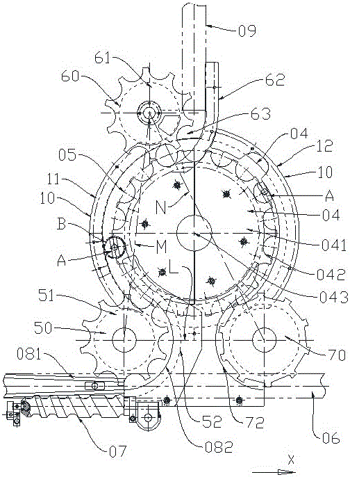
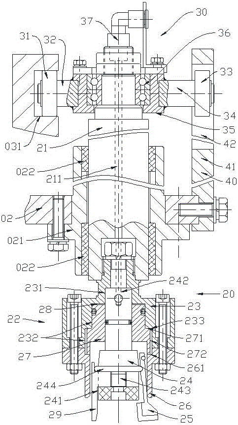
[0065] Such as figure 1 as shown, figure 1 A schematic top view of the structural principle of the automatic palletizing device provided by a specific embodiment of the present invention; figure 2 A schematic cross-sectional view of some parts of the automatic palletizing device provided by a specific embodiment of th...


PUM


Abstract

The invention discloses an automatic holder separating device and a corresponding holder separating method. The automatic holder separating device comprises a rack, a bottle feeding stirring wheel assembly, a holder discharging stirring wheel assembly, a bottle discharging stirring wheel assembly, a rotary seat and a cam, and the rotary seat and the cam are arranged on the rack. The cam is provided with a cam groove. A rotary platform is arranged on the rotary seat, and provided with a large stirring wheel with a stirring groove in the periphery. The rack is provided with a barrier assembly matching the stirring groove, and the stirring groove, the rotary platform and the barrier assembly match to form a plurality of bottle bearing positions. The rotary seat is provided with grasping mechanisms matching the bottle bearing positions. The grasping mechanisms are provided with lifting driving mechanisms. The cam groove comprises a first descending segment, a first ascending segment, a second descending segment and a second ascending segment which are arranged in sequence so that the grasping mechanisms can sequentially grasp bottles, lift the grasped bottles, put the grasped bottles back to the bottle bearing positions with bottle holders shifted out and carry out non-load lifting, and therefore the bottles and the bottle holders are separated. The invention further provides a holder separator with the automatic holder separating device or method, a linkage production line and packaging equipment.

Description

technical field [0001] This application relates to the technical field of packaging machinery, and specifically relates to an automatic palletizing device and a palletizing method mainly used in a linkage production line. The automatic palletizing device and palletizing method are generally used in food, daily chemical, pharmaceutical or In the linkage production line of medical and other manufacturing industries. [0002] The present application also relates to a palletizing machine and a linked production line using the above palletizing method or automatic palletizing device. [0003] In addition, the present application also relates to a packaging device using the above-mentioned palletizing method or automatic palletizing device. Background technique [0004] In the linkage production line of bottled products such as pharmaceuticals, food, daily chemicals or medical treatment, for the production of bottled products, especially in the process of conveying, transferring,...

Claims


Application Information

Patent Timeline
Patent Type & Authority Patents(China)
IPC IPC(8): B67C3/24B67C3/22B65G47/90
Inventor 阳年生冯涛
Owner 湖南华尔特今朝科技有限公司
Why Eureka
Try Eureka