Dead head production device with automatic assembling and material taking functions

A technology of automatic assembly and production equipment, which is applied in the direction of casting molding equipment, metal processing equipment, manufacturing tools, etc., can solve the problems of low production efficiency and inability to realize automatic assembly and molding, and achieve the effect of convenient automatic assembly and flexible setting mode

Active Publication Date: 2017-06-27
长兴鼎峰铸材科技股份有限公司
View PDF8 Cites 4 Cited by
  • Summary
  • Abstract
  • Description
  • Claims
  • Application Information

AI Technical Summary

Problems solved by technology

[0004] The purpose of the present invention is to address the deficiencies of the prior art. By setting the telescopic device and the supporting mechanism supporting the forming mold, it overc

Method used


Image

  • Dead head production device with automatic assembling and material taking functions
  • Dead head production device with automatic assembling and material taking functions
  • Dead head production device with automatic assembling and material taking functions

Examples


Embodiment 1

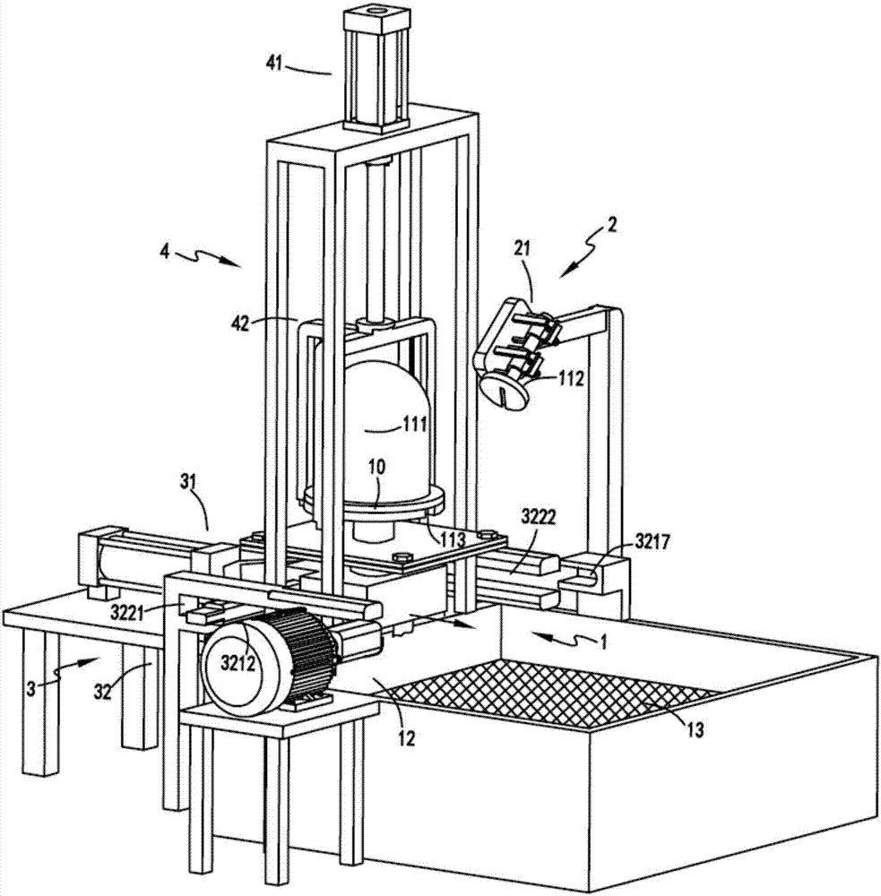
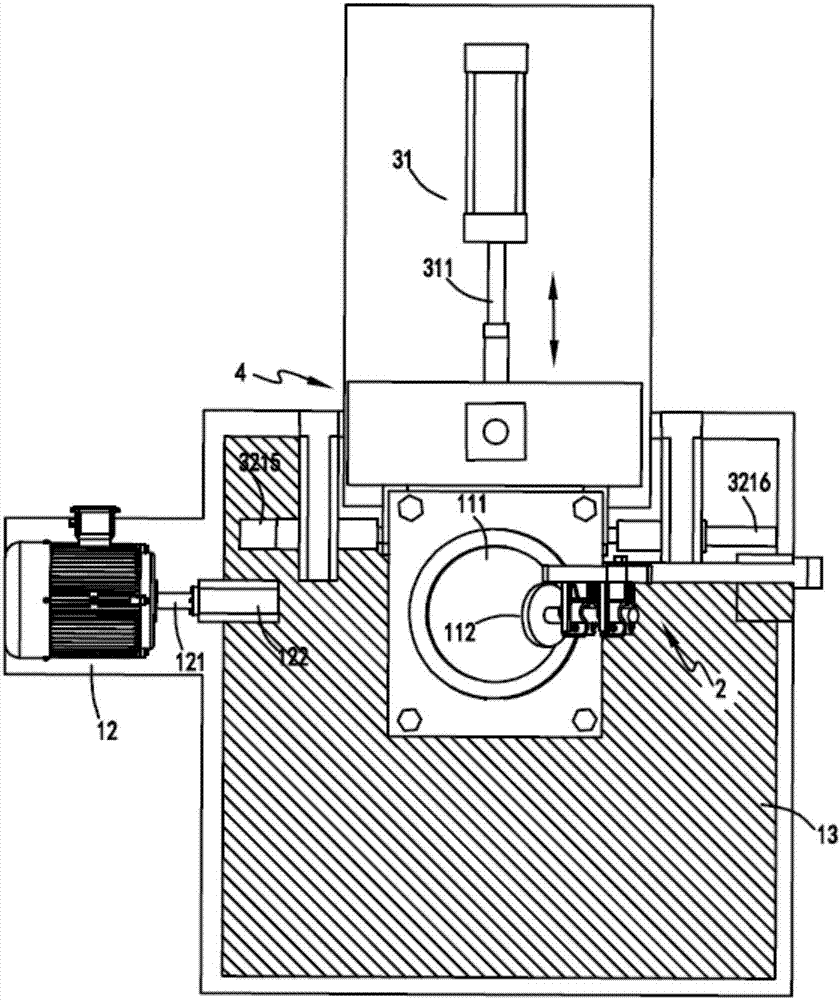
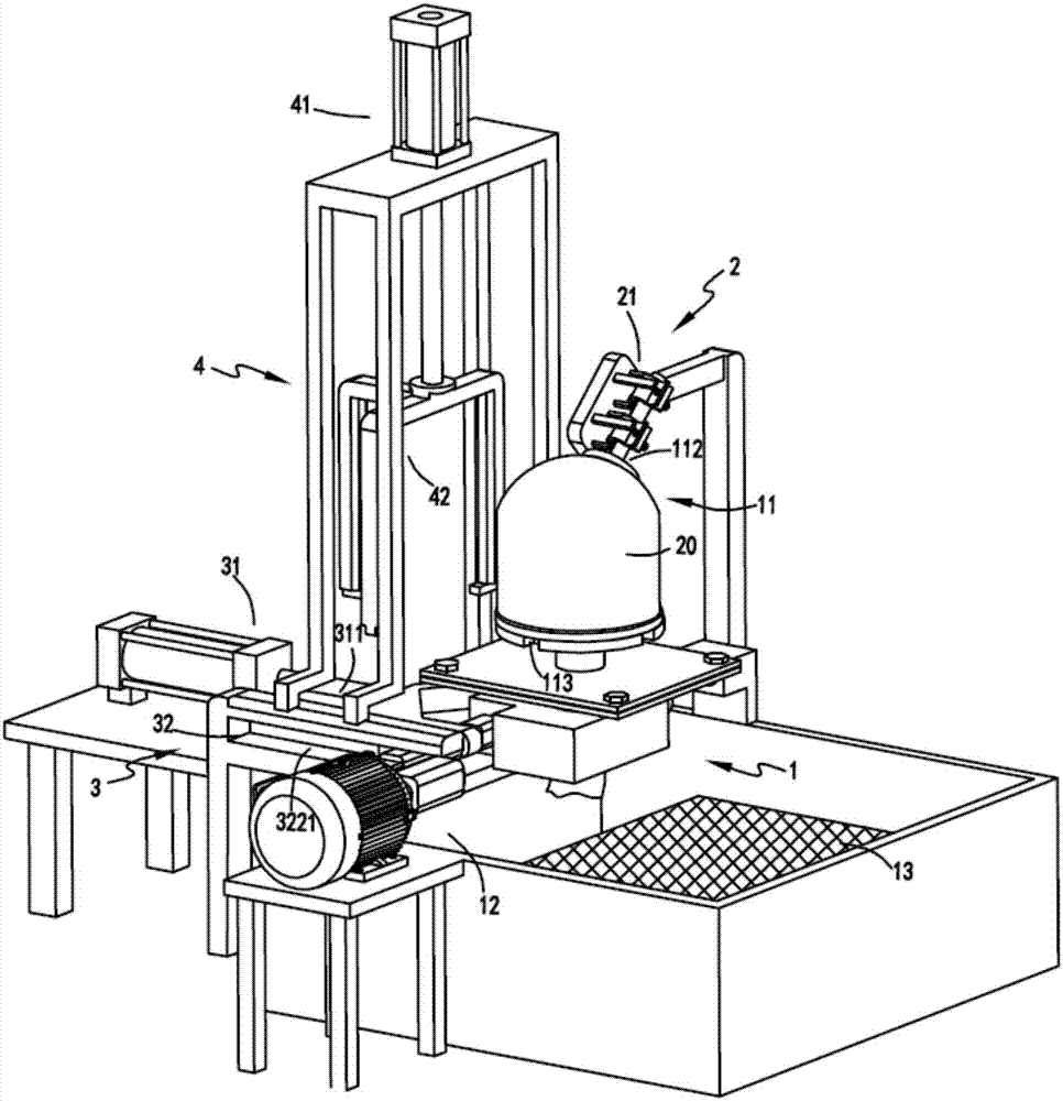
[0038] figure 1 It is a schematic structural diagram of the initial state of the riser production equipment with automatic assembly and reclaiming functions, figure 2 It is a top view diagram of the riser production equipment with automatic assembly and reclaiming functions, image 3 It is a schematic diagram of the structure of the riser production equipment with automatic assembly and reclaiming functions when it is automatically separated, Figure 4 It is a schematic diagram of the push-pull part and the forming part, Figure 5 It is a schematic diagram of the enlarged structure when the forming mold and the forming cover are matched, Figure 6 It is a schematic diagram of the structure when the rotating device drives the forming device to rotate, Figure 7 It is a structural schematic diagram of the clamping part of the molding cover, Figure 8 Schematic diagram of the structure of the molded cover. Such as figure 1 , figure 2 , image 3 , Figure 4 , Figure 5...

Embodiment 2

[0056] Such as figure 1 , figure 2 , image 3 , Figure 4 , Figure 5 , Figure 6 , Figure 7 and Figure 8 As shown, the components that are the same as or corresponding to those in the first embodiment are marked with the corresponding reference numerals in the first embodiment. For the sake of simplicity, only the differences from the first embodiment will be described below. The difference between the second embodiment and the first embodiment is that the forming cover 112 includes a cover body 1122 and a clamping rod 1123 for fastening with the clamping unit 21; the end of the clamping rod 1123 A limit rod 1124 is also provided, and correspondingly, a limit hole 221 cooperating with the limit rod 1124 is provided on the support frame 22, and the cooperation between the limit hole 221 and the limit rod 1124 can make The position of the forming cover 112 is fixed, avoiding the situation that the clamping unit 21 cannot firmly clamp the forming cover 112 due to the f...


PUM


Abstract

The invention relates to a dead head production device with automatic assembling and material taking functions. The dead head production device comprises a forming part, a forming cover clamping part, a push-pull part and a dead head taking-out part. The forming part comprises a forming device and a rotation device. The forming device comprises a forming die and a forming cover. The forming cover clamping part comprises a plurality of clamping units. The push-pull part is arranged on one side of the forming part. When forming is needed, the push-pull part is used for pushing the forming die to move forwards to be installed with the forming cover in a matched manner, and the forming cover is separated from the clamping units. When material taking is needed, the push-pull part is used for pulling the forming die to move backwards, the forming cover is buckled and connected to the clamping units, and the forming die is separated from the forming cover. The push-pull part comprises a telescopic device and a supporting mechanism. The dead head taking-out part comprises a lifting device and a material supporting device. The problems that in the dead head forming process, the forming cover needs to be manually dismounted and mounted, the production efficiency is low, and automatic assembling forming cannot be achieved.

Description

technical field [0001] The invention relates to the technical field of riser production equipment, in particular to a riser production equipment with automatic assembly and material retrieving functions. Background technique [0002] The riser made of low thermal conductivity material is called thermal insulation riser. Compared with ordinary riser, the metal liquid in the riser has a longer solidification time and better feeding effect. There are many shapes and structures of thermal insulation risers. At present, the principle of adsorption molding is generally used in the manufacture of thermal insulation risers. In the pulp pool turned over by the adsorption molding equipment, the slurry pump vacuumizes the inside of the mold, and the slurry is attached to the surface of the mold to form a thermal insulation riser. mouth, the existing insulation riser production equipment generally has a low degree of automation and low production efficiency. [0003] A Chinese utility ...

Claims


Application Information

Patent Timeline
IPC IPC(8): B22C9/08
CPCB22C9/088
Inventor 樊新峰
Owner 长兴鼎峰铸材科技股份有限公司
Why Eureka
Try Eureka