Automatic oil edging machine with accurate positioning

A technology of accurate positioning and oil edge machine, which is applied to the surface coating liquid device, small raw hide/large raw hide/leather/fur treatment, leather surface treatment, etc., which can solve the problem of affecting the quality of oil edge, uneven oiling, Low work efficiency and other problems, to achieve the effect of high degree of automation, improved reliability, and high product quality

Active Publication Date: 2012-10-10
SHENZHEN HOCHUEN TECH
View PDF5 Cites 4 Cited by
  • Summary
  • Abstract
  • Description
  • Claims
  • Application Information

AI Technical Summary

Problems solved by technology

[0002] In the prior art, the oil edge of leather and other workpieces is generally manually operated. This oil edge process has low work efficiency and uneven oiling; although there are also equipment that adopts automatic oil edge in the prior art, this automatic oil edge The oil edge machine generally adopts the method of passing materials or simulating manual operation. In addition to only oiling regular-shaped leather, it must go through multiple processes, especially for irregular shapes or curved corners. It is even more time-consuming for the oil edge of the part, and most of the existing automatic oil edge machines are semi-automatic, and many tasks must be manually intervened to realize the cooperation between various processes, which is inefficient and cannot be completed during the oil edge process. It can avoid the misalignment of the workpiece, that is to say, when the workpiece is edged, it is easy to be misaligned, resulting in inaccurate positioning, which affects the quality of the edge

Method used


Image

  • Automatic oil edging machine with accurate positioning
  • Automatic oil edging machine with accurate positioning
  • Automatic oil edging machine with accurate positioning

Examples


Embodiment 1

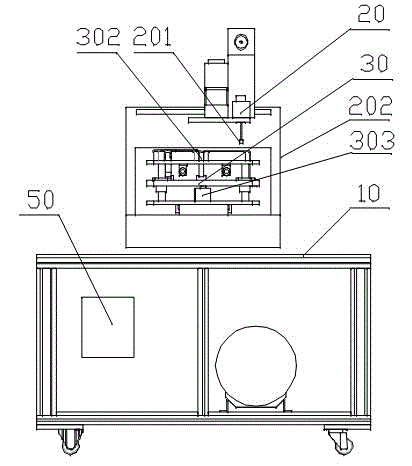
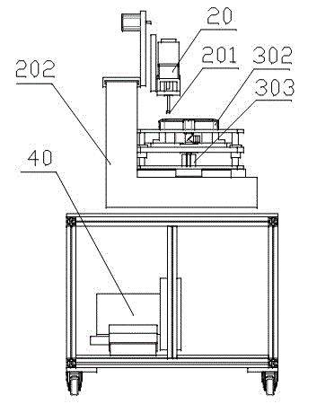
[0030] like figure 1 and figure 2 As shown, this example provides an automatic oil edge machine with precise positioning, including:

[0031] Rack 10;

[0032] The oil edge head assembly 20 installed on the frame 10, the oil edge head assembly 20 includes the oil nozzle head 201 and the mechanical shaft 201 for realizing the two-dimensional movement of the oil nozzle head 201;

[0033]A workpiece positioning device 30 for realizing oil edge positioning. The workpiece positioning device 30 is arranged on the frame 10 and under the oil edge head assembly 20. The workpiece positioning device 30 includes a positioning column 302 and a positioning cylinder 303. The positioning The column 302 is arranged on the side of the workpiece positioning device 30, and the positioning cylinder 303 is used to move the workpiece placement surface up and down relative to the positioning column 302; and,

[0034] The control member 50 is used to control the oil edge process of the oil edge he...

Embodiment 2

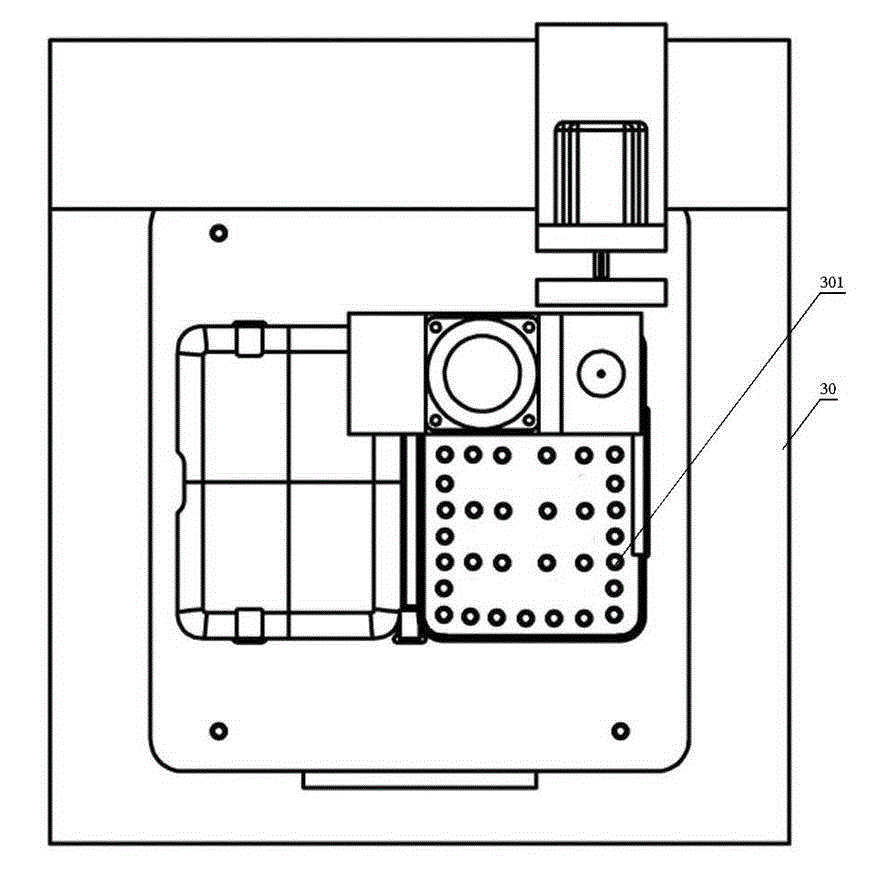
[0043] like image 3 As shown, on the basis of Embodiment 1, the air holes 301 in this example are arranged symmetrically on the workpiece placement surface of the workpiece positioning device 30 .

[0044] The workpiece placement surface of the workpiece positioning device 30 is provided with air holes 301, and the air holes 301 are symmetrically arranged, that is, symmetrically arranged according to the shape of the workpiece, preferably symmetrically arranged from the periphery to the inner periphery of the workpiece shape, so that Through mutual symmetrical suction, the positioning of the workpiece is more reliable, no misalignment occurs, the reliability of the oil edge process is improved, and the misalignment problem is very well avoided.

[0045] A further improvement of this example is that the arrangement of the air holes 301 on the workpiece placement surface of the workpiece positioning device 30 is dense on the outside and sparse on the inside.

[0046] The arran...

Embodiment 3

[0048] On the basis of Embodiment 1 or Embodiment 2, the oil nozzle head 201 in this example is connected to the control member 50 , and the control member 50 controls the fuel injection speed of the oil nozzle head 201 . The control member 50 controls the oil injection speed of the oil nozzle head 201, which is convenient to control the oil injection speed of the oil nozzle head 201 according to different oil edge requirements or workpiece materials, improves the degree of customization, and has a high degree of humanized design.

[0049] The further improvement of this example is that oil holes are uniformly arranged on the circumference of the nozzle head 201 , and the nozzle head 201 realizes the self-rotating movement with adjustable speed during the oil edge process.

[0050] Oil holes are evenly arranged on the circumference of the oil nozzle head 201. During the oil edge process, the oil nozzle head 201 realizes the speed-adjustable autorotation, that is, when the oil e...


PUM


Abstract

The invention provides an automatic oil edging machine with accurate positioning. The automatic oil edging machine comprises a frame, an oil edging nose assembly arranged on the frame, a workpiece positioning device and a control component, wherein the oil edging nose assembly comprises an oil nozzle and a mechanical shaft which is used for realizing two-dimensional motion of the oil nozzle; the workpiece positioning device is arranged on the frame and under the oil edging head assembly, and comprises a positioning column and a positioning cylinder; the positioning column is arranged on the lateral side of the workpiece positioning device; the positioning cylinder is used for realizing up and down movement of a workpiece placement surface relative to the positioning column; and the control component is used for controlling the oil edging process of the oil edging nose assembly, and controlling the positioning cylinder and the oil edging nose assembly to realize positioning fit of workpiece oil edging. According to the automatic oil edging machine, the automatic oil edging process to workpieces can be realized without manual intervention, and the automatic degree is high; on the basis of the automatic oil edging process, the problem of workpiece dislocation can be well solved by virtue of the drop between the positioning column and the workpiece placement surface, the positioning is accurate, and the oil edging products have high quality.

Description

technical field [0001] The invention relates to an oil edge machine, in particular to an automatic oil edge machine with precise positioning. Background technique [0002] In the prior art, the oil edge of leather and other workpieces is generally manually operated. This oil edge process has low work efficiency and uneven oiling; although there are also equipment that adopts automatic oil edge in the prior art, this automatic oil edge The oil edge machine generally adopts the method of passing materials or simulating manual operation. In addition to only oiling regular-shaped leather, it must go through multiple processes, especially for irregular shapes or curved corners. It is even more time-consuming for the oil edge of the part, and most of the existing automatic oil edge machines are semi-automatic, and many tasks must be manually intervened to realize the cooperation between various processes, which is inefficient and cannot be completed during the oil edge process. I...

Claims


Application Information

Patent Timeline
Patent Type & Authority Applications(China)
IPC IPC(8): B05C5/00B05C13/02C14C15/00C14C11/00
Inventor 柳朝晖余前晋谢志强李伟杨红
Owner SHENZHEN HOCHUEN TECH
Why Eureka
Try Eureka