
Mold device and method for bridge deck slab

A bridge deck, bridge-specific technology, applied in bridges, bridge parts, bridge construction, etc., can solve the problems of poor sealing effect and loose sealing parts

Inactive Publication Date: 2020-10-27
CCCC SHEC FIRST HIGHWAY ENG
View PDF0 Cites 0 Cited by
  • Summary
  • Abstract
  • Description
  • Claims
  • Application Information

AI Technical Summary

Problems solved by technology

[0004] In order to solve the above problems, the present invention provides a mold device and method for the bridge deck, which effectively avoids the loosening of the sealing parts and the sealing parts under the impact of concrete on some customized bridge deck molds in the prior art. There is a gap in the sealing place and the concrete enters to make the sealing effect not good.

Method used


Image

  • Mold device and method for bridge deck slab
  • Mold device and method for bridge deck slab
  • Mold device and method for bridge deck slab

Examples


Embodiment 1

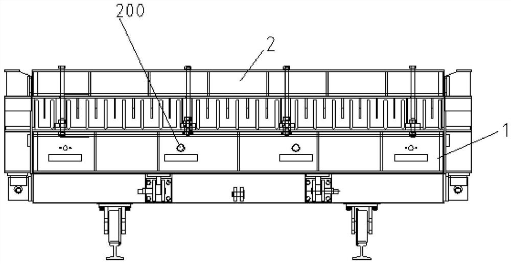
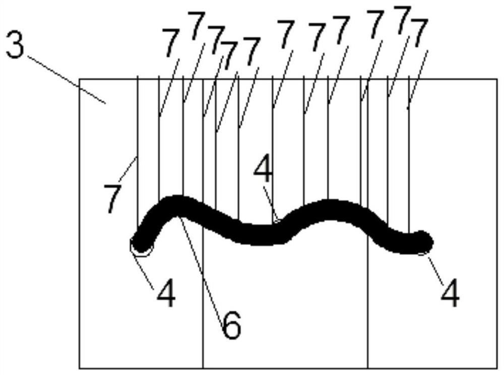
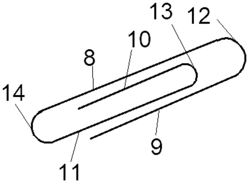
[0045] like Figure 1-Figure 4 As shown, the mold device for the bridge deck includes a bridge deck forming mold, and the bridge deck forming mold includes a bottom mold 1, and the bottom mold 1 is a rectangular frame, and the four sides of the rectangular frame are all rectangular plates. Four side molds 2 are respectively connected to the top walls of the four sides of the bottom mold 1. The four side molds 2 are all rectangular flat plates, and the four side molds 2 are enclosed to form a rectangular frame structure. The side molds 2 are respectively located at the front end of the top wall of the bottom mold 1, the rear end of the top wall of the bottom mold 1, the left end of the top wall of the bottom mold 1 and the right end of the top wall of the bottom mold 1. A rectangular frame structure is formed with four side molds 2;

[0046] The main body of the rebar frame is arranged in the rectangular frame structure, the rebar frame includes several rebars, and the rebars ...

Embodiment 2

[0057] like Figure 1-Figure 4 As shown, the mold device for the bridge deck includes a bridge deck forming mold, and the bridge deck forming mold includes a bottom mold 1, and the bottom mold 1 is a rectangular frame, and the four sides of the rectangular frame are all rectangular plates. Four side molds 2 are respectively connected to the top walls of the four sides of the bottom mold 1. The four side molds 2 are all rectangular flat plates, and the four side molds 2 are enclosed to form a rectangular frame structure. The side molds 2 are respectively located at the front end of the top wall of the bottom mold 1, the rear end of the top wall of the bottom mold 1, the left end of the top wall of the bottom mold 1 and the right end of the top wall of the bottom mold 1. A rectangular frame structure is formed with four side molds 2;

[0058] The main body of the rebar frame is arranged in the rectangular frame structure, the rebar frame includes several rebars, and the rebars ...


PUM


Abstract

The invention relates to a mold device and method for a bridge deck slab. The mold device comprises a bridge deck slab forming mold, the bridge deck slab forming mold comprises a bottom mold, four side molds are connected to the top walls of the four sides of the bottom mold respectively, and a rectangular frame structure is formed by a first bottom mold and the four side molds; a main body of a steel bar frame is arranged in the rectangular frame structure; the top of the steel bar frame is lower than the top of the bottom mold; and a steel shell with an opening in the top is arranged on thesteel bar frame, a plurality of first through holes are formed in the inner wall with the opening in the top, second through holes are formed in the outer wall of the bottom mold, the number of the second through holes is consistent with that of the first through holes, the second through holes correspond to the first through holes in a one-to-one mode, and each second through hole is attached toand connected with the corresponding first through hole. Defects that in the prior art, blocking pieces of molds for some customized bridge deck slabs are loosened under the action of concrete impact,gaps exist at blocking positions of the blocking pieces, concrete enters the gaps, and a blocking effect is poor are effectively overcome.

Description

technical field [0001] The invention relates to the technical field of molds for bridge decks, in particular to a mold device and method for bridge decks. Background technique [0002] The bridge deck, also known as the roadway deck, is a load-bearing structure that directly bears the wheel pressure of the vehicle. In terms of structure, it is usually integrally connected with the ribs of the main beam and the diaphragm, so that it can not only transmit the vehicle load to the main beam, but also constitute a component of the main beam section, and ensure the overall function of the main beam. Bridge decks are generally made of reinforced concrete. [0003] Specifically, for bridges erected on road sections with complex topography, a large number of prefabricated bridge decks are required. To construct a prefabricated bridge deck, it is necessary to use concrete to pour the mold of the bridge deck, and the mold often includes a bottom mold at the bottom , a side form is co...

Claims


Application Information

Patent Timeline
Patent Type & Authority Applications(China)
IPC IPC(8): E01D19/12E01D21/00
CPCE01D19/125E01D21/00
Inventor 祝新顺王鑫刘晓雨
Owner CCCC SHEC FIRST HIGHWAY ENG
Learn More