Optical medical device

A medical device and light source technology, applied in the field of optical medical treatment, can solve the problems of high treatment cost, inappropriateness, poor luminous uniformity, etc., and achieve the effects of good luminous uniformity, convenient use and portability, and long treatment period

Pending Publication Date: 2020-10-30
GUAN YEOLIGHT TECH CO LTD
View PDF10 Cites 1 Cited by
  • Summary
  • Abstract
  • Description
  • Claims
  • Application Information

AI Technical Summary

Problems solved by technology

[0004] Therefore, the present invention aims to solve the technical problems that the photomedical devices in the prior art are inconveni

Method used


Image

  • Optical medical device
  • Optical medical device
  • Optical medical device

Examples


Example Embodiment

[0056] Example 1

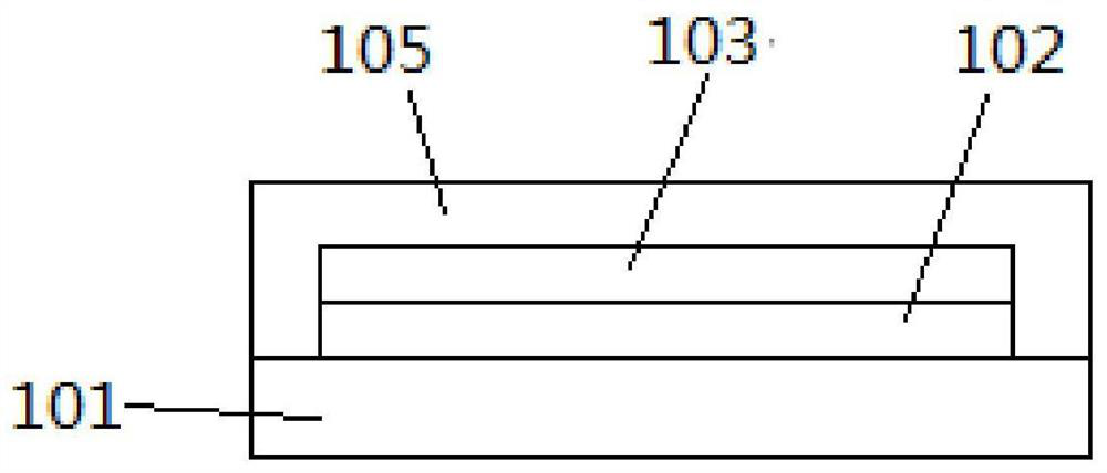
[0057] Such as figure 1 with Figure 18b As shown, the present invention provides an optical medical device comprising a light source unit 10 and a power source unit 20. The light source unit 10 is connected to the power source unit 20. The light source unit 10 in turn includes a base cloth 101, a connection layer 102, a light source layer 103, and a cover layer. 105, the connection layer 102 is laminated on the base cloth 101, the light source layer 103 is laminated on the connection layer 102, the covering layer 105 is a light-transmitting structure, which is laminated on the light source layer 103, and the light source layer 103 and the connection layer 102 are completely covered The power supply unit is used to light the light source layer and perform phototherapy treatment on the affected part of the body; the covering layer 105 preferably adopts a heat-insulating and light-transmitting structure, adopts a heat-insulating transparent fabric, and its transmi...

Example Embodiment

[0070] Example 2

[0071] This embodiment provides an optical medical device. The main structure of the light source part is the same as that of Embodiment 1, and the same parts will not be repeated. The difference between this embodiment and Embodiment 1 is:

[0072] Such as Figure 8 As shown, the power source part 20 is integrated with the light source part 10, and the light source part 10 and the power source part 20 are both arranged at the same base cloth 101 position. The power source part is a paper battery, and the power source part 20 can directly supply power to the light source part 10. The light source unit 10 is turned on by controlling the switch on the power source unit 20, and the power source unit 20 and the light source unit 10 are connected by wires.

[0073] In addition, the light source part 10 and the power source part 20 can also adopt a direct bonding design, such as Picture 9 As shown, the power supply part 20 is arranged on the outer side of the base fabr...

Example Embodiment

[0075] Example 3

[0076] This embodiment provides an optical medical device. The main structure of the light source part is the same as that of Embodiment 1, and the same parts will not be repeated. The difference between this embodiment and Embodiment 1 is:

[0077] Such as Picture 10 As shown, a wireless power supply chip 1032 is added to the light source part 10, and the power source part 20 and the light source part 10 are connected by wireless power supply. For example, the light source is bound to an FPC, and the FPC is connected to an NFC coil. The power source part is preferably an NFC smart terminal. The light source layer can be lighted up on the NFC coil. After the power source part 20 and the light source part 10 are directly attached, the mobile terminal can wirelessly power the light source part without wires. The controller for adjusting the emission wavelength, time and brightness of the light source layer can be provided in the power supply part or the light sou...


PUM

PropertyMeasurementUnit
Luminous wavelengthaaaaaaaaaa

Abstract

The invention discloses an optical medical device which comprises a light source part and a power supply part, the light source part is electrically connected with the power supply part; the light source part comprises base cloth, a connecting layer, a light source layer and a covering layer, the connecting layer is laminated on the base cloth, the light source layer is laminated on the connectinglayer, the covering layer is of a light-transmitting structure, is laminated on the light source layer and covers the light source layer and the connecting layer, and the power supply part is used for lightening the light source layer. The light source layer has the characteristics of good light-emitting uniformity, lightness, thinness, bendability, flexibility, stretchability and the like and can be completely attached to a to-be-phototreated part of a patient so that the problems that an existing optical medical device is inconvenient to wear and damages normal tissues can be well solved, the design is more user-friendly, and the comfort and safety of user experience are guaranteed.

Description

technical field [0001] The invention relates to the field of optical medical technology, in particular to an optical medical device. Background technique [0002] Photodynamic therapy is a method of directly using light or using light and drugs to treat diseases, which has been applied in clinical medicine. There are two main methods of photodynamic therapy, one is direct phototherapy, and the other is medical treatment in which light and drugs (also known as photosensitizers) act synergistically. Among them, direct phototherapy is to directly irradiate the affected area with one kind of light or multiple kinds of light to sterilize, disinfect, promote cell metabolism, promote cell regeneration, promote cell secretion of some chemical substances (such as serotonin, etc.) and promote blood circulation. etc., thereby obtaining the effect of treating diseases. The medical process of the synergistic effect of light and drugs is that the photosensitizer absorbed by the tissue i...

Claims


Application Information

Patent Timeline
IPC IPC(8): A61N5/06
CPCA61N5/062A61N2005/0651A61N2005/0664
Inventor 康建喜许显斌张国辉朱映光马永强穆东华胡永岚
Owner GUAN YEOLIGHT TECH CO LTD
Why Eureka
Try Eureka