
Profile stretch bending equipment

A profile and equipment technology, applied in the field of profile stretch bending equipment, can solve the problems of reducing work efficiency, wasting manpower, increasing labor force, etc., and achieve the effect of improving efficiency, ensuring the quality of stretch bending, and improving the degree of cooperation

Pending Publication Date: 2021-01-29
GUANGDONG G CLEF BENDING TECH CO LTD
View PDF0 Cites 1 Cited by
  • Summary
  • Abstract
  • Description
  • Claims
  • Application Information

AI Technical Summary

Problems solved by technology

At present, in the profile stretch bending process, the adjustment of the position between the profile and the drawing arm is mostly done manually, which not only increases the labor force, wastes manpower, but also reduces work efficiency

Method used


Image

  • Profile stretch bending equipment
  • Profile stretch bending equipment
  • Profile stretch bending equipment

Examples


Embodiment 1

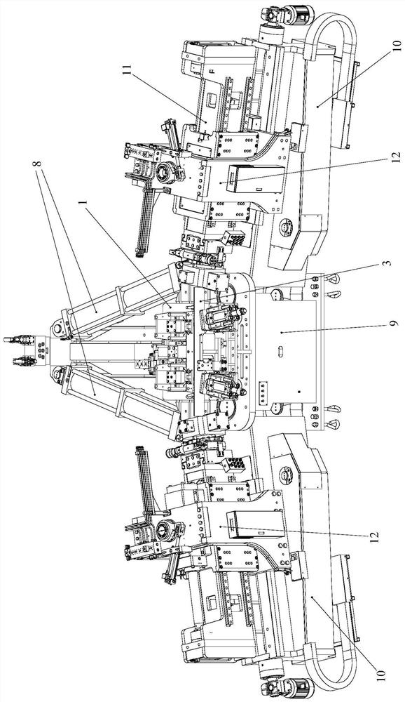
[0071] Such as Figure 1 to Figure 23 As shown, the profile stretch bending equipment of the present invention comprises:

[0072] working platform;

[0073]Left swing arm assembly and right swing arm assembly for clamping and stretching both ends of the profile;

[0074] And a swing arm cylinder assembly 9 for driving the swing of the left swing arm assembly and the right swing arm assembly;

[0075] Wherein, the left swing arm assembly and the right swing arm assembly are respectively located on both sides of the working platform, and the swing arm oil cylinder assembly 9 is connected with the left swing arm assembly and the right swing arm assembly.

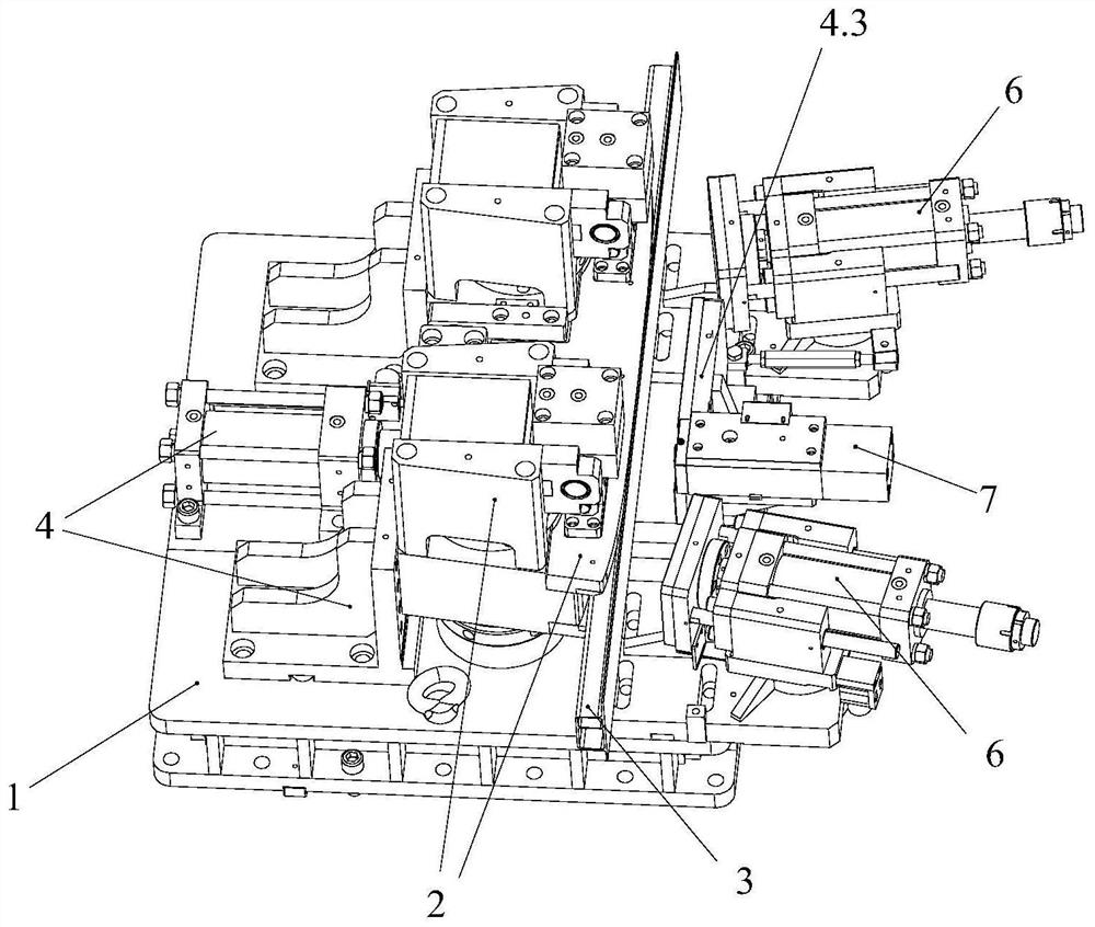
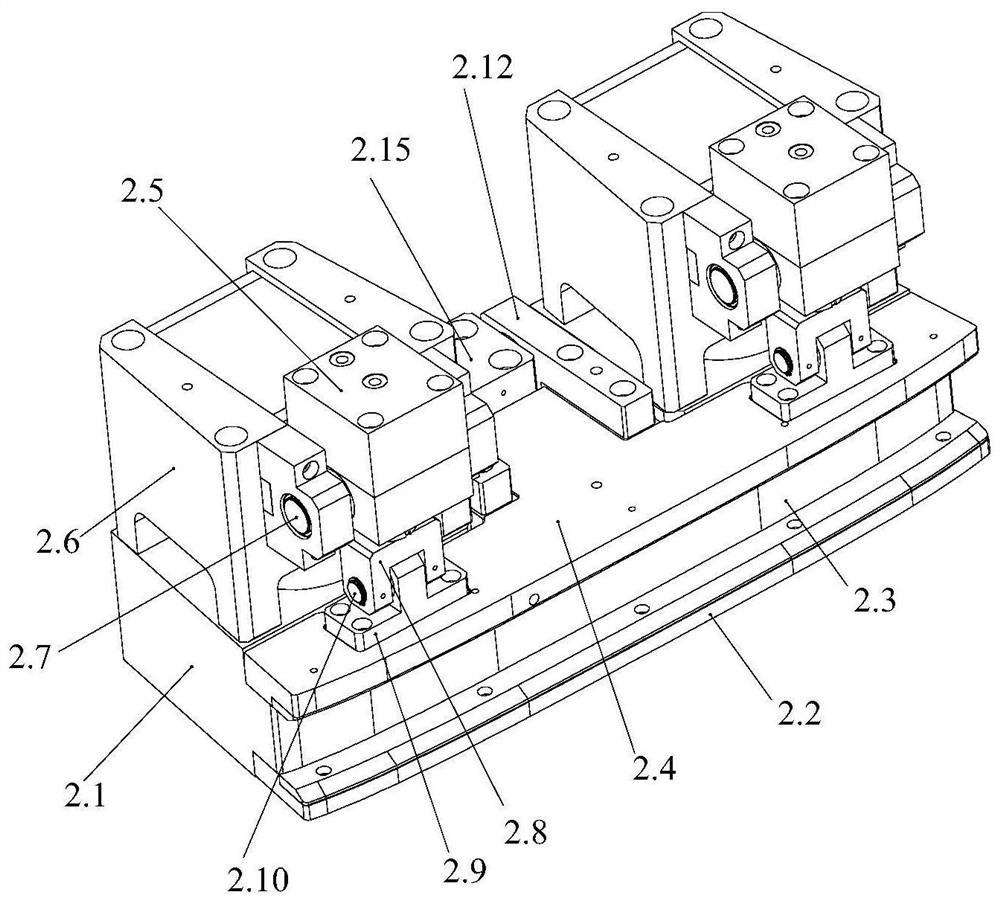
[0076] The working platform includes a platform base 8, a base 1, a pressing mechanism 2 for longitudinally positioning the profile 3, a horizontal positioning mechanism 4 for horizontally positioning the profile 3, and a horizontal positioning mechanism 4 for stretching and bending the profile 3. The tangent point position...

Embodiment 2

[0109] This embodiment differs from Embodiment 1 only in that: Figure 24 As shown, the mandrel of this embodiment includes a joint unit, the joint unit includes a joint part 12.8 and a mandrel rod 12.9, the joint part 12.8 is a movable detachable structure, and the joint part 12.8, the mandrel rod 12.9 and the mandrel are connected The rods 12.1 are in turn hinged and detachably connected.

[0110] The mandrel of this embodiment is suitable for the stretch bending process of only one cavity structural profile.

[0111] Other structures of this embodiment are consistent with Embodiment 1.

Embodiment 3

[0113] This embodiment differs from Embodiment 1 only in that: Figure 25 As shown, the joint part of the mandrel in this embodiment, the mandrel pull rod and the mandrel connecting rod 12.1 are connected sequentially, specifically: the joint part 1 of the joint unit 1 is hinged with the mandrel pull rod 12.2, and the joint part 2 of the joint unit 2 is connected with the mandrel rod 12.2. Mandrel tie rod two 12.5 are hinged, and mandrel tie rod one 12.2 and mandrel tie rod two 12.5 are connected with mandrel connecting rod 12.1 and are integrally structured to form a mandrel body.

[0114] Other structures of this embodiment are consistent with Embodiment 1.


PUM


Abstract

The invention provides profile stretch bending equipment. The profile stretch bending equipment comprises: a working platform, a left swing arm assembly and a right swing arm assembly, used for clamping and stretching the two ends of a profile; and swing arm oil cylinder assemblies. The left swing arm assembly and the right swing arm assembly are located on the two sides of the working platform correspondingly. The swing arm oil cylinder assemblies are connected with the left swing arm assembly and the right swing arm assembly. The working platform comprises a platform base, a base, a pressingmechanism used for longitudinally positioning the profile, a horizontal positioning mechanism used for positioning the profile in the horizontal direction, and a tangent point positioning mechanism used for positioning a tangent point when the profile is subjected to stretch bending. Each of the left swing arm assembly and the right swing arm assembly comprises a swing arm base body and a material pulling arm mechanism arranged on the swing arm base body. The swing arm oil cylinder assemblies are connected with the swing arm base body so as to drive the swing arm base body to swing. The profile stretch bending equipment can achieve high-precision and high-efficiency stretch bending of the profile and has the advantages of being easy and convenient to operate and high in practicability, and therefore the stretch bending quality of the profile is guaranteed.

Description

technical field [0001] The invention relates to the technical field of profile stretch bending processing, and more specifically relates to a profile stretch bending equipment. Background technique [0002] At present, metal profiles with a certain amount of bending are widely used in production and life. For example, in building decoration, metal profiles with a specific amount of bending are required as fixing devices. For example, they are also widely used in the manufacture of aircraft and automobiles. Applications. In order to obtain a metal profile with a predetermined amount of bending, it is necessary to perform stretch bending on the metal profile. [0003] Most of the domestic profile stretch bending process includes three stages of pre-stretching, bending and supplementary stretching. Remove the external force and take out the material. Among them, the working platform is the main operating platform of the stretch bending machine, which plays a very important r...

Claims


Application Information

Patent Timeline
Patent Type & Authority Applications(China)
IPC IPC(8): B21D11/02B21D11/22
CPCB21D11/02B21D11/22
Inventor 郑晓宏
Owner GUANGDONG G CLEF BENDING TECH CO LTD
Learn More