
Pre-molding seat structure and injection molding machine with same

A technology of pre-molded seat and ring structure, which is applied in the field of injection molding machines, can solve the problems of affecting the working quality of bearings and difficult control of locking torque of lock nuts, etc.

Inactive Publication Date: 2021-02-12
ZHUHAI GREE INTELLIGENT EQUIP CO LTD +1
View PDF5 Cites 0 Cited by
  • Summary
  • Abstract
  • Description
  • Claims
  • Application Information

AI Technical Summary

Problems solved by technology

[0004] The main purpose of the present invention is to provide a pre-molded seat structure and an injection molding machine with it, to solve the problem that the locking torque of the lock nut in the pre-molded seat structure in the prior art is not easy to control and thus affect the working quality of the bearing

Method used


Image

  • Pre-molding seat structure and injection molding machine with same
  • Pre-molding seat structure and injection molding machine with same
  • Pre-molding seat structure and injection molding machine with same

Examples


Embodiment Construction

[0024] It should be noted that, in the case of no conflict, the embodiments in the present application and the features in the embodiments can be combined with each other. The present invention will be described in detail below with reference to the accompanying drawings and examples.

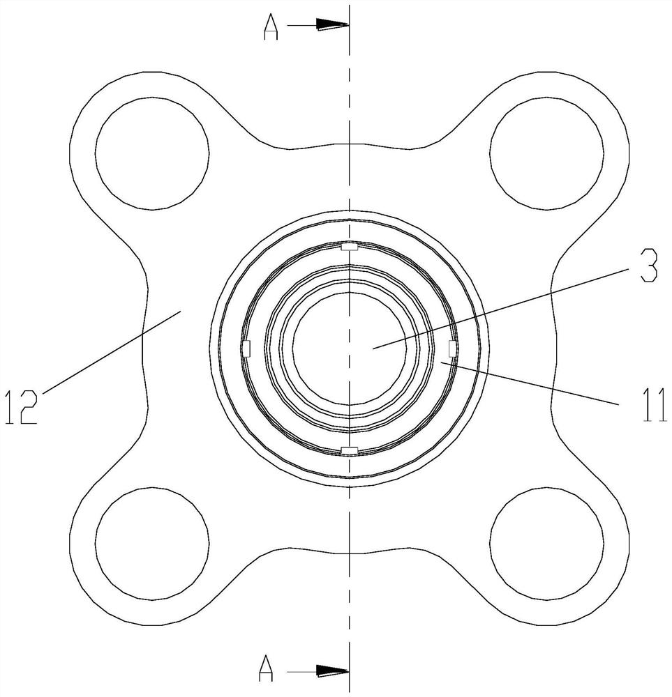
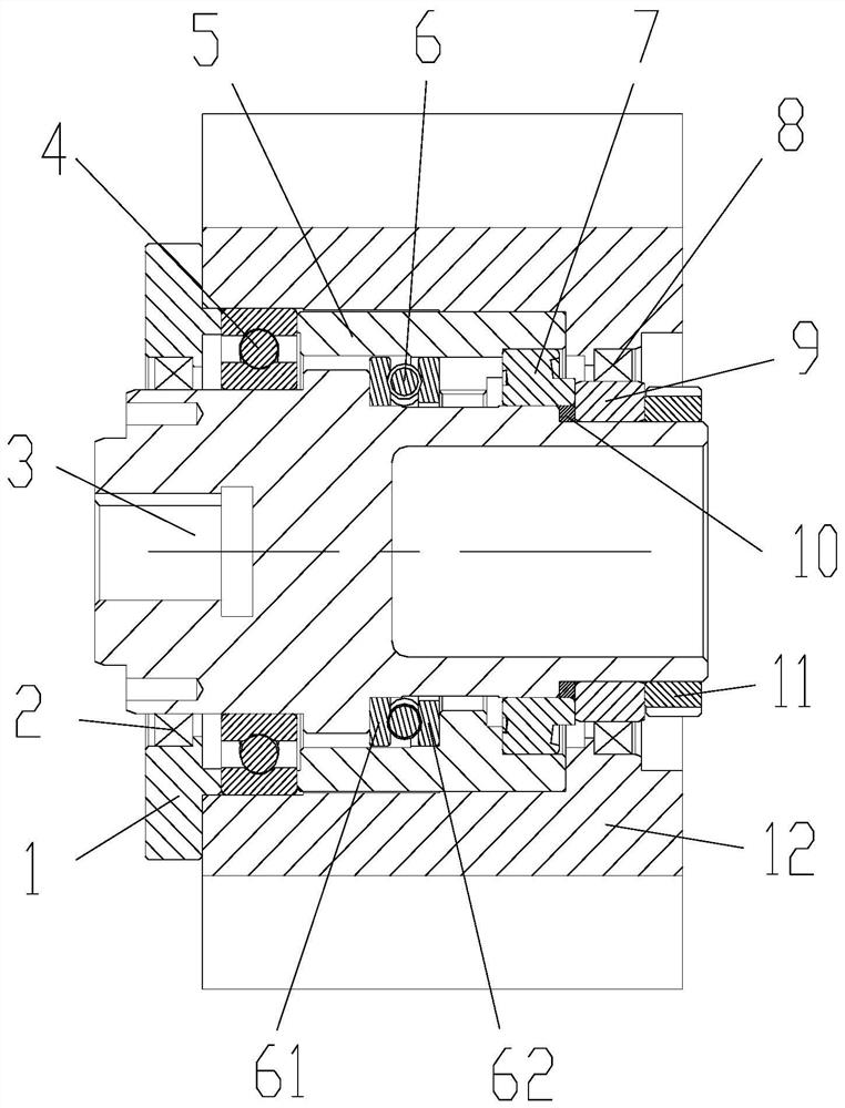
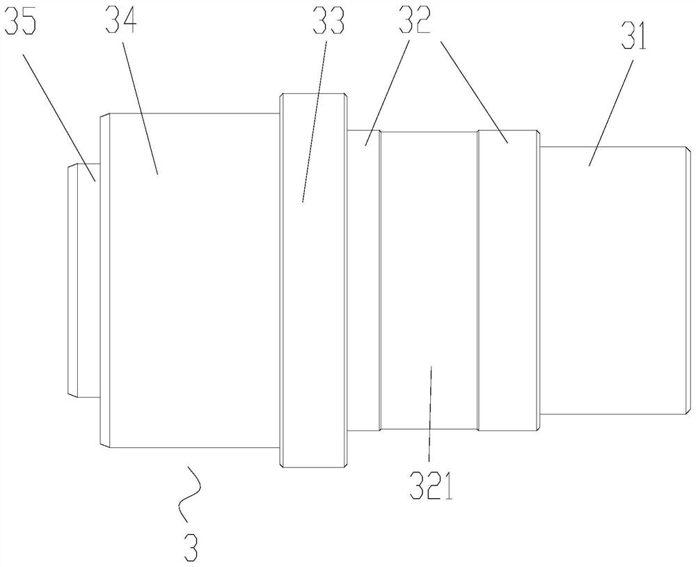
[0025] Such as Figure 1 to Figure 5 As shown, the present invention provides a pre-molded seat structure, including: a pre-molded seat 12, the pre-molded seat 12 is used to be sleeved on the transmission shaft 3; the first bearing 7, the first bearing 7 is sleeved on the transmission shaft 3 and between the pre-plastic seat 12 and the transmission shaft 3; the locking member 11, the locking member 11 is arranged on one side of the first bearing 7, and the locking member 11 is adjustable along the axial position of the transmission shaft 3, To axially lock the first bearing 7; the spacer 10, the spacer 10 is arranged on the inner side of the inner ring of the first bearing 7, and the spacer 10...


PUM


Abstract

The invention provides a pre-molding seat structure and an injection molding machine with the pre-molding seat structure. The pre-molding seat structure comprises a pre-molding seat which is used forbeing arranged on a transmission shaft in a sleeving manner, a first bearing arranged on the transmission shaft in a sleeving manner and located between the pre-molding seat and the transmission shaft, a locking piece arranged on one side of the first bearing and adjustably arranged in the axial position of the transmission shaft so as to axially lock the first bearing, and an isolation pad arranged on the inner side of the inner ring of the first bearing, wherein the isolation pad is fixedly arranged relative to the transmission shaft, so that after the locking piece pushes the inner ring ofthe first bearing by a preset distance in the axial direction of the transmission shaft, part of pressure of the locking piece is borne through the isolation pad. According to the technical scheme, the problem that in the prior art, the locking torque of a locking nut in a pre-molding seat structure is not easy to control, and consequently the working quality of a bearing is affected is solved.

Description

technical field [0001] The invention relates to the field of injection molding machines, in particular to a premolding seat structure and an injection molding machine with the same. Background technique [0002] In the existing technology, in order to save costs, the bearing configuration of the pre-molded seat is "thrust bearing + angular contact bearing + deep groove ball bearing", the thrust bearing directly contacts with the pre-molded seat, and the preload of the thrust bearing is locked The nut and the transmission shaft are realized by tightening the thrust bearing and the angular contact bearing relative to each other through the screwing of the thread pair. [0003] Due to the high quality and irregular shape of the pre-molded seat, the disassembly and maintenance of the drive shaft and other parts on the pre-plastic seat is not convenient enough, and the locking torque of the lock nut is not easy to control. The pre-tightening force on the bearing is too large, wh...

Claims


Application Information

Patent Timeline
IPC IPC(8): B29C45/17B29C45/84
CPCB29C45/17B29C45/84
Inventor 黎秀郁莫玉麟赵永政宋佳庆孟萌
Owner ZHUHAI GREE INTELLIGENT EQUIP CO LTD
Learn More