Fluid tank having internal evaporator
An evaporator and fluid technology, applied in the field of fluids, can solve problems such as increased maintenance costs, and achieve the effects of reducing energy consumption, preventing conversion, and preventing low temperature brittleness
- Summary
- Abstract
- Description
- Claims
- Application Information
AI Technical Summary
Problems solved by technology
Method used
Image

Examples
no. 1 example
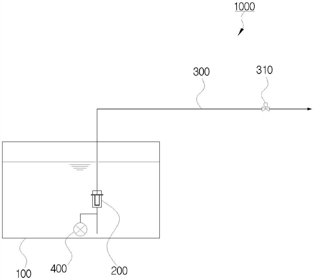
[0038] image 3 is a diagram showing a fluid tank with an internal evaporator according to a first embodiment of the present invention, and Figure 4 is another diagram showing a fluid tank with an internal evaporator according to the first embodiment of the present invention.
[0039] refer to image 3 with Figure 4 , a fluid tank 1000 with an internal evaporator according to a first embodiment of the present invention as a configuration for converting a stored liquid fluid into a gaseous fluid and delivering the gaseous fluid to a place of use generally includes a tank body 100, Conversion unit 200 and delivery unit 400 .
[0040] The tank body 100 is configured to store liquid fluid. At this time, the liquid fluid stored in the tank body 100 can be liquefied natural gas (LNG). Therefore, the tank body 100 can maintain an ultra-low temperature for storing LNG.
[0041] Of course, the tank body 100 of the fluid tank 1000 with an internal evaporator according to the first...
no. 2 example
[0057] Figure 5 is a diagram showing a fluid tank with an internal evaporator according to a second embodiment of the present invention, and Image 6 is another diagram showing a fluid tank with an internal evaporator according to a second embodiment of the present invention.
[0058] refer to Figure 5 with Image 6 , according to the second embodiment of the present invention, the conversion unit 200 of the fluid tank 1000 with an internal evaporator includes a conversion unit body 210, a high-temperature heating medium pipeline 220, a low-temperature heating medium pipeline 230 and a thermal insulation unit, wherein the conversion unit body 210 The supplied liquid fluid is heat-exchanged with the heating medium to be converted into a gaseous fluid. The high-temperature heating medium pipeline 220 supplies the heating medium to the conversion unit body 210 from the outside, and the low-temperature heating medium pipeline 230 will be in the conversion unit body 210 with th...
no. 3 example
[0076] Figure 7 is a diagram showing a fluid tank with an internal evaporator according to a third embodiment of the present invention, and Figure 8 is another diagram showing a fluid tank with an internal evaporator according to a third embodiment of the present invention.
[0077] refer to Figure 7 with Figure 8 , the conversion unit 200 of the fluid tank 1000 with an internal evaporator according to the third embodiment of the present invention further includes an exhaust pipe 260 allowing external air to flow into the high-temperature heating medium pipe 220 .
[0078] That is, when the gaseous fluid is not delivered to the place of use and the operation of the fluid tank is stopped, the heating medium will remain in the conversion unit 200, and thus it is necessary to remove the heating medium to minimize damage to the fluid stored inside the tank body 100. Effects of liquid fluids.
[0079]For this reason, the conversion unit 200 of the fluid tank 1000 with an in...
PUM
 Abstract
Description
Claims
Application Information
 - R&D
- Intellectual Property
- Life Sciences
- Materials
- Tech Scout
- Unparalleled Data Quality
- Higher Quality Content
- 60% Fewer Hallucinations
Browse by: Latest US Patents, China's latest patents, Technical Efficacy Thesaurus, Application Domain, Technology Topic, Popular Technical Reports.
© 2025 PatSnap. All rights reserved.Legal|Privacy policy|Modern Slavery Act Transparency Statement|Sitemap|About US| Contact US: help@patsnap.com