Machining lathe

A lathe and processing cavity technology, applied in the field of lathes, can solve problems such as splashing, affecting processing quality, surrounding safety, and surrounding hazards, and achieve the effects of protecting self-safety, avoiding self-triggering, and facilitating cleaning and concentration

Pending Publication Date: 2021-03-02
焦超锦
View PDF1 Cites 3 Cited by
  • Summary
  • Abstract
  • Description
  • Claims
  • Application Information

AI Technical Summary

Problems solved by technology

[0006] In order to solve the technical problems existing in the background technology, the present invention proposes a processing lathe, which solves the problem that during the processing of the existing processing lathe, waste chips will be splashed at a very large initial speed due to the influence of the workpiece's own rotational speed during processing. It is easy to cause harm to the surrounding area, affecting the processing quality and surrounding safety

Method used


Image

  • Machining lathe
  • Machining lathe
  • Machining lathe

Examples


Embodiment

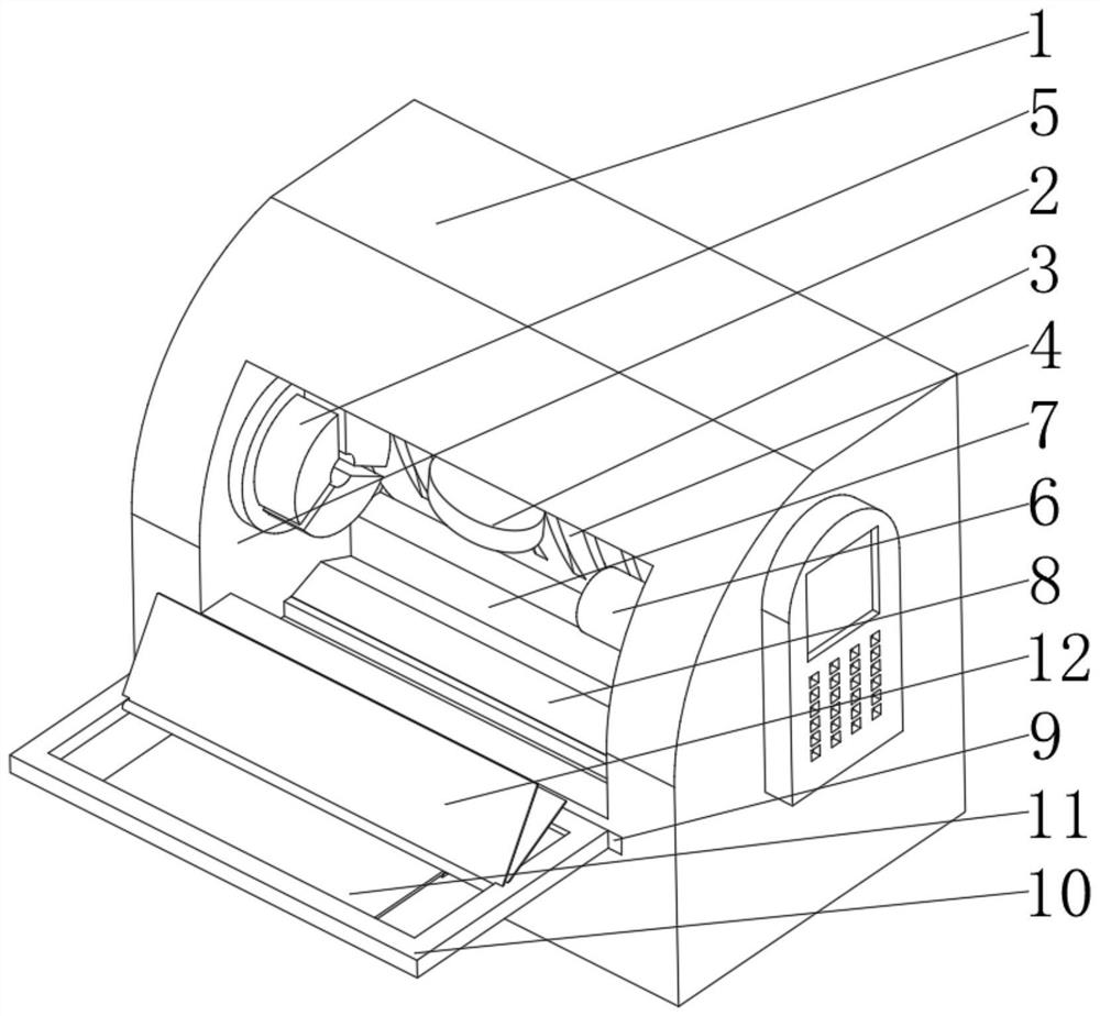
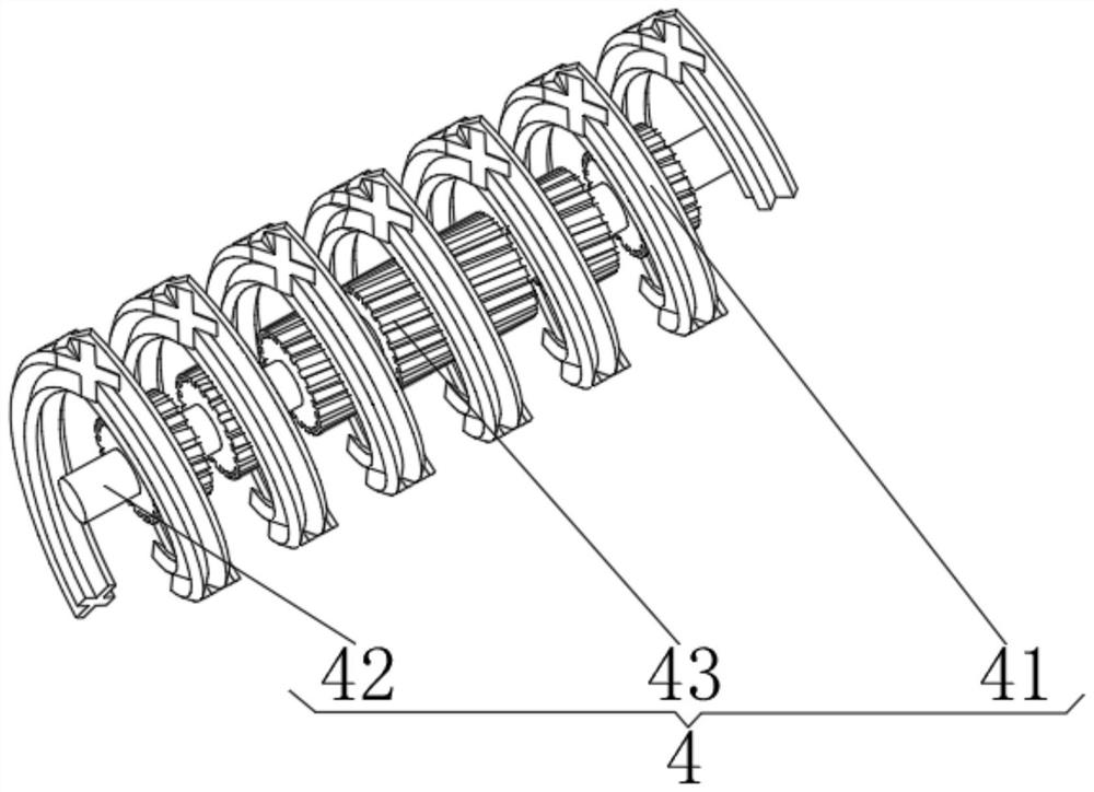
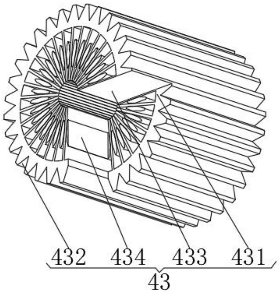
[0039] Such as Figure 1-6 As shown, a processing lathe proposed by the present invention includes a lathe body 1, a processing chamber 2 is provided in the middle of the front of the lathe body 1, a processing tool 3 is fixedly connected to the middle of the top of the processing chamber 2, and the back of the processing chamber 2 is A diversion mechanism 4 is fixedly connected, a three-jaw chuck 5 is provided in the middle of the left inner wall of the processing chamber 2, and an auxiliary fixing mechanism 6 is movably connected to the middle of the inner wall of the right inner wall of the processing chamber 2, and the middle of the bottom of the processing chamber 2 is The position is provided with a bottom groove 7, and the bottom of the inner cavity of the bottom groove 7 is fixedly connected with an electromagnet 8, and the front of the inner cavity of the bottom groove 7 is located above the electromagnet 8 and is provided with a cleaning groove 9, and the inner surfac...


PUM


Abstract

The invention discloses a machining lathe which comprises a lathe body, a machining cavity is formed in the middle of the front face of the lathe body, a flow guide mechanism is fixedly connected to the back face of an inner cavity of the machining cavity, an auxiliary fixing mechanism is movably connected to the middle of the inner wall of the right side of the inner cavity of the machining cavity, an electromagnet is fixedly connected to the bottom of an inner cavity of a bottom groove, a cleaning groove is formed in the position, located above the electromagnet, of the front face of the inner cavity of the bottom groove, a waste disc is slidably connected to the inner surface of the cleaning groove, a balance mechanism is fixedly connected to the middle of the bottom of an inner cavityof the waste disc, and a collecting mechanism is fixedly connected to the top of the balance mechanism. The invention relates to the technical field of lathes. A rotating air screen is formed throughair flow generated by rotation of the equipment, so that splashing of sweeps is blocked, and the periphery is protected; and through wind power generation, electromagnetic force is generated to adsorbthe sweeps, so that he sweeps are cleaned in a centralized mode, the sweeps are prevented from being scattered and distributed in the equipment, and cleaning is convenient.

Description

technical field [0001] The invention relates to the technical field of lathes, in particular to a processing lathe. Background technique [0002] Lathe, a machine tool that uses a turning tool to turn a rotating workpiece. Drills, reamers, reamers, taps, dies and knurling tools can also be used for corresponding processing on the lathe. At present, the existing lathe generally clamps the raw material rod through the chuck, and then turns the workpiece through the cutting tool. [0003] According to Chinese patent CN105014473A, through the setting of the scraper and the drive assembly, the scraper can be effectively driven to move back and forth on the inner wall of the frame shell through the drive assembly, so that the scraper can be attached to the inner wall of the rack shell through the scraper. The scraps on the rack are scraped off to enter the chip removal groove below, and then sent out through the conveyor belt, so that the scraps on the inner wall of the rack she...

Claims


Application Information

Patent Timeline
Patent Type & Authority Applications(China)
IPC IPC(8): B23B25/00B23Q11/00
CPCB23B25/00B23Q11/00
Inventor 焦超锦
Owner 焦超锦
Why Eureka
Try Eureka