Conveying feeding device

A feeder and conveyor chain technology, applied in the field of aluminum ingot processing, can solve the problems of lower production efficiency, aluminum ingot material damage, slipping, etc., and achieve the effect of improving feeding efficiency, reducing load capacity, and uniform efficiency

Inactive Publication Date: 2017-05-24
重庆龙之火科技有限公司
View PDF0 Cites 0 Cited by
  • Summary
  • Abstract
  • Description
  • Claims
  • Application Information

AI Technical Summary

Problems solved by technology

However, the design of the feeding device in the production of the prior art is unreasonable, and the conveyed aluminum ingot material is easy to slip during the conveying process, causing damage to the aluminum ingot material, increasing the labor capacity, increasing the production cost and reducing the production efficiency.

Method used


Image

  • Conveying feeding device
  • Conveying feeding device

Examples


Embodiment 1

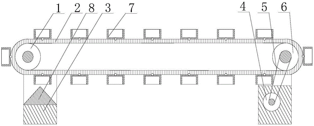
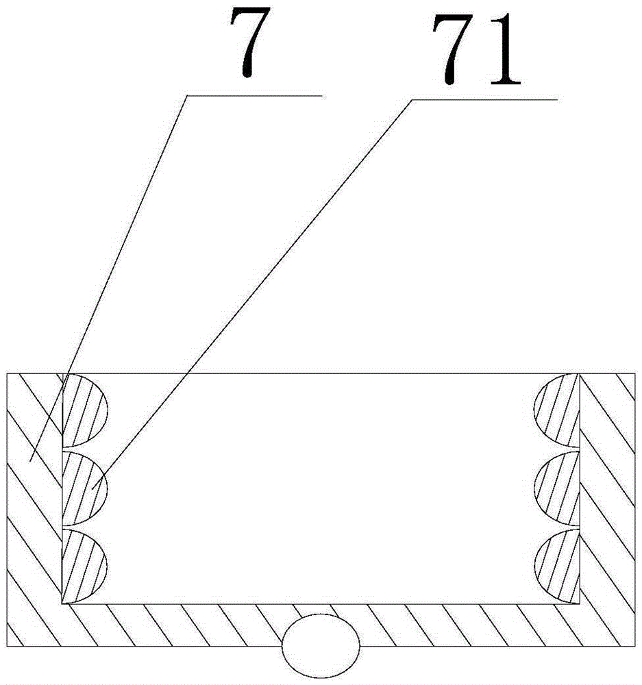
[0020] Such as figure 1 and figure 2 As shown, the present embodiment includes two U-shaped support bases 3 arranged at intervals and a transmission chain plate 2, the main roller 6 and the slave roller 1 are respectively rotated and arranged on the two support bases 3, and the two ends of the transmission chain plate 2 Placed in the U-shaped area of ​​the support seat 3 and matched with the main roller 6 and the slave roller 1, the conveying chain plate 2 is hingedly provided with a plurality of hoppers 7 whose interior matches the shape of the aluminum ingot, and also includes Motor 4, the motor 4 is placed at the bottom of the support seat 3 and its output end is connected and matched with the rotating shaft of the main roller 6 through the belt 5; a collection block 8 is installed at the bottom of the U-shaped area of ​​the support seat 3 corresponding to the slave roller 1 , the upper end of the collection block 8 is composed of two connected inclined surfaces, and the ...


PUM


Abstract

Disclosed is a conveying feeding device. The conveying feeding device comprises two supporting bases and a conveying chain plate. A driving roller and a driven roller are arranged on the supporting bases in a rotating mode respectively. The two ends of the conveying chain plate are arranged in U-shaped regions of the supporting bases and matched with the driving roller and the driven roller. A plurality of hoppers are arranged on the conveying chain plate in a hinged mode, and the interior of each hopper is matched with the appearance of the corresponding aluminum ingot. A motor is arranged at the bottom of one supporting base, and the output end of the motor is connected with a rotating shaft of the driving roller through a belt and matched with the rotating shaft. A collecting block is installed at the bottom of the U-shaped region of the supporting base corresponding to the driven roller, the upper end of the collecting block is formed by two inclined planes which are connected with each other, and the point of connection between the inclined planes exactly faces the conveying chain plate. In the conveying process, the aluminum ingots and the hoppers correspond in a one-to-one mode, the phenomenon that according to a conventional conveying feeding device, aluminum ingots are distributed on a conveying belt in a scattered mode when conveying is conducted is avoided, the step that manual sorting is conducted again in the feeding process is omitted, and feeding of the aluminum ingots can be effectively conducted.

Description

technical field [0001] The invention relates to aluminum ingot processing, in particular to a conveying feeder. Background technique [0002] At present, the automatic feeding device is one of the indispensable main components in the aluminum ingot processing equipment. Its main function is to transport the aluminum ingot materials between the processing equipment, so that the aluminum ingot materials can be processed and produced in time. However, the design of the feeding device in the production of the prior art is unreasonable, and the conveyed aluminum ingot material is easy to slip during the conveying process, causing damage to the aluminum ingot material, increasing labor capacity, increasing production cost and reducing production efficiency. Contents of the invention [0003] The purpose of the present invention is to provide a conveying feeder, which facilitates the rapid conveying of aluminum ingots and simultaneously achieves the purpose of improving feeding e...

Claims


Application Information

Patent Timeline
Patent Type & Authority Applications(China)
IPC IPC(8): B65G17/12
Inventor 何源兰
Owner 重庆龙之火科技有限公司
Why Eureka
Try Eureka