Power cable recycling and cleaning device

A cleaning device and power cable technology, applied in the direction of electronic waste recycling, recycling technology, circuits, etc., can solve the problems of poor cleaning effect, low cleaning efficiency, and increased equipment production costs, and achieve reasonable structure, good effect, and reduced Effect of replacement cycle

Pending Publication Date: 2021-03-12
万金国
View PDF0 Cites 6 Cited by
  • Summary
  • Abstract
  • Description
  • Claims
  • Application Information

AI Technical Summary

Problems solved by technology

[0003] At present, most of the cleaning methods for cables are manual cleaning, which has low cleaning efficiency and poor cleaning effect. There are also some cleaning equipment on the market. Although the cleaning efficiency has improved, its efficiency and effect still need to be improved, especially some cleaning equipment. Multiple devices, which will increase the production cost of the device, so we designed a power cable recovery and cleaning device to solve the above problems

Method used


Image

  • Power cable recycling and cleaning device
  • Power cable recycling and cleaning device
  • Power cable recycling and cleaning device

Examples


Embodiment 1

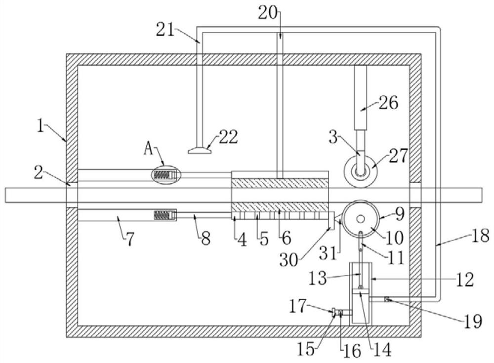
[0027] refer to Figure 1-3 , a power cable recycling cleaning device, including a cleaning box 1, the cleaning box 1 is filled with an appropriate amount of water; both ends of the cleaning box 1 are provided with conveying holes 2 to facilitate the passage of cables; the cleaning box 1 is provided with a round The central axis of the tube 4 and the circular tube 4 are on the same axis as the transverse axes of the two conveying holes 2, so that the cables pass through the circular tube 4 conveniently, and then the cables are conveniently installed.

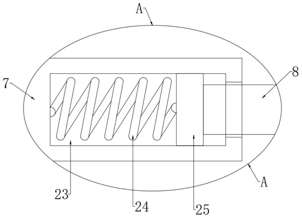
[0028] Cleaning cotton 6 is installed in the round pipe 4, and a plurality of water leakage holes 5 are provided through the bottom of the round pipe 4 to facilitate the discharge of clear water; the round pipe 4 is connected with the inner wall of the cleaning box 1 through two reset supports, and the reset supports include The first crossbar 7 fixed on the inner wall of the cleaning box 1 is provided with a hollow cavity 23 in...

Embodiment 2

[0037] refer to Figure 4-5 The difference between this embodiment and Embodiment 1 is that in this embodiment, the opposite sides of the two second crossbars 8 are fixedly connected with a brush 32, and the side of the brush 32 close to the cable can be set as an arc that matches the cable. , two brushes 32 are arranged oppositely; the circular tube 4 is fixedly connected with a ring 33, the inner wall of the ring 33 is equipped with a sponge 34, and the inner wall of the cleaning box 1 is equipped with a top-shaped hollow tube 35, Described hollow cylinder 35 is matched with sponge 34, and the two ends of described hollow cylinder 35 are all equipped with annular baffle; Wherein hollow cylinder 35 and circular ring 33 coincide with the axis of round pipe 4; Wherein the front and rear ends of hollow cylinder 35 are fixed If the support rod is connected, the support rod is fixedly connected with the inner wall of the cleaning box 1 .

[0038] In this embodiment, the brush 32 ...


PUM


Abstract

The invention discloses a power cable recovering and cleaning device. The power cable recovering and cleaning device comprises a cleaning box; conveying holes are formed in two ends of the cleaning box in a penetrating mode; a round pipe is arranged in the cleaning box; cleaning cotton is installed in the round pipe; the round pipe is connected with the inner wall of the cleaning box through two reset supporting pieces; a piston cylinder is installed at the inner bottom of the cleaning box; a piston is connected with the interior of the piston cylinder in a sliding mode; a piston rod is hingedto the upper end of the piston; a water inlet pipe is installed on the piston cylinder; a water inlet one-way valve is installed on the water inlet pipe; and a water outlet pipe is installed on the piston cylinder. The power cable recovering and cleaning device is reasonable in structure, by adopting one piece of power equipment, cleaning cable can be conveyed for being conveniently cleaned, clear water can be pumped for flushing the cable, brushing of the outer wall of the cable can be achieved, and dust on the outer part of the cable can be effectively and efficiently cleaned; and the investment of power equipment is reduced, and the production cost can be reduced.

Description

technical field [0001] The invention relates to the technical field of cable recovery, in particular to a power cable recovery and cleaning device. Background technique [0002] In order to save resources, the recycled cables with better performance must be reused, and the surface of the recycled cables is basically covered with dirt, dust and other dirt, so the recycled cable coils should be cleaned before being used again. use. [0003] At present, most of the cleaning methods for cables are manual cleaning, which has low cleaning efficiency and poor cleaning effect. There are also some cleaning equipment on the market. Although the cleaning efficiency has improved, its efficiency and effect still need to be improved, especially some cleaning equipment. Multiple devices will increase the production cost of the device, so we designed a power cable recovery and cleaning device to solve the above problems. Contents of the invention [0004] The purpose of the present inve...

Claims


Application Information

Patent Timeline
Patent Type & Authority Applications(China)
IPC IPC(8): B08B1/02B08B1/00B08B3/02B08B13/00H01B15/00
CPCB08B1/002B08B1/006B08B1/02B08B3/02B08B13/00H01B15/00Y02W30/82
Inventor 万金国
Owner 万金国
Why Eureka
Try Eureka