Water-oil composite rail
A compound rail and water-oil technology, applied in the direction of charging system, adding non-fuel substances to fuel, fuel injection device, etc., can solve the problems of high difficulty and high cost, achieve low manufacturing cost, reduce processing workload and occupy The effect of small air intake space
- Summary
- Abstract
- Description
- Claims
- Application Information
AI Technical Summary
Problems solved by technology
Method used
Image

Examples
Embodiment 1
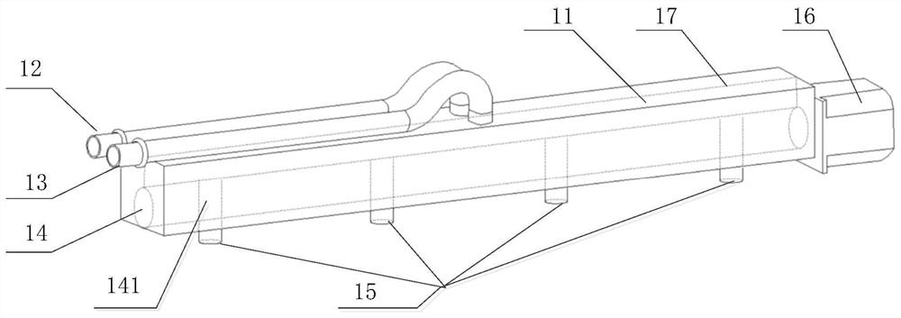
[0054] figure 1 A water-oil composite rail provided in the embodiment of this application. Such as figure 1 As shown, the water-oil composite rail may include: a water-oil composite rail body 11 , an oil inlet pipe 12 , a water inlet pipe 13 , a control shaft 14 , at least one nozzle installation hole 15 , and a motor 16 .
[0055]A fuel chamber and a water chamber are formed inside the water-oil composite rail body 11. The oil inlet pipe 12 leads to the fuel chamber, and the water inlet pipe 13 leads to the water chamber. The fuel chamber is provided with an oil outlet, and the water chamber is provided with a water outlet.
[0056] The control shaft 14 is arranged inside the water-oil composite rail body 11 , and at least one communication structure is arranged on the control shaft 14 , and the at least one communication structure corresponds to the position of at least one nozzle installation hole 15 .
[0057] When the communication structure is in the first communicatio...
Embodiment 2
[0069] The embodiment of the present application provides a water-oil composite rail. In the water-oil composite rail provided in this embodiment, the motor 16 is arranged at one end of the control shaft 14. When the rotating shaft of the motor 16 rotates, it drives the control shaft 14 to rotate, so that at least one communication structure is in the first communication state and the second communication state. switch between.
[0070] Specifically, for example, when the rotating shaft of the motor 16 rotates clockwise, it drives the control shaft 14 to rotate clockwise, so that the fuel chamber communicates with the corresponding communication structure through the oil outlet hole, the communication structure communicates with the corresponding nozzle mounting hole 15, and the fuel chamber The oil inside flows to the nozzle through the oil outlet hole, the corresponding communication structure, and the corresponding nozzle installation hole 15, so as to realize the oil injec...
Embodiment 3
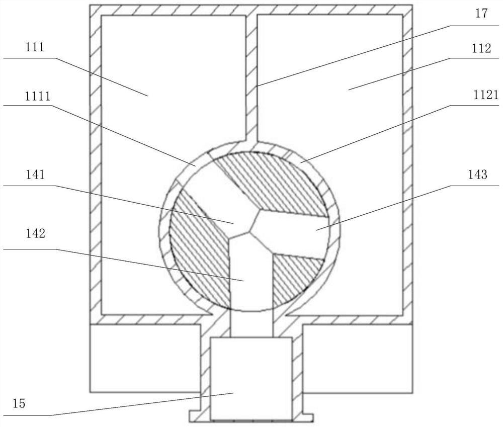
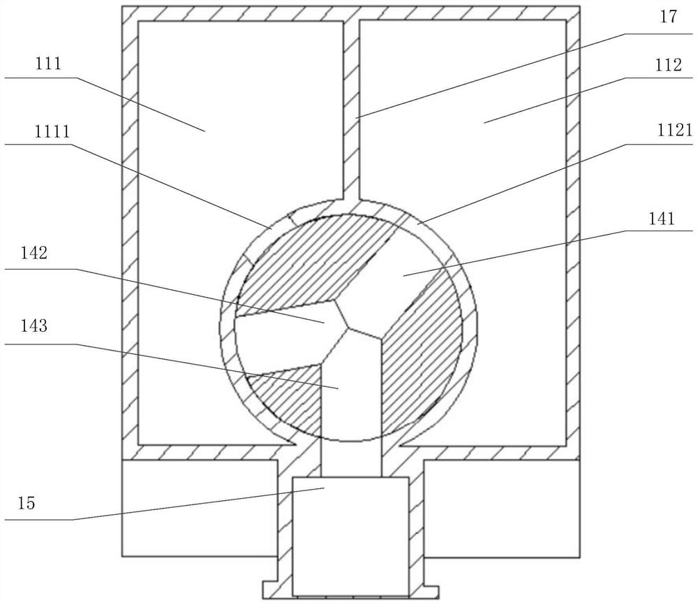
[0074] The embodiment of the present application provides a water-oil composite rail. The water-oil composite rail provided in this embodiment further provides a specific structure of the communication structure on the basis of the second embodiment of the present application. Combine below Figure 2a with Figure 2b The water-oil composite rail provided in the embodiment of this application is described in detail.
[0075] Figure 2a A cross-sectional view of the water-oil composite rail with the communication structure in the first communication state provided by the embodiment of the present application. Figure 2b A cross-sectional view of the water-oil composite rail with the communication structure in the second communication state provided by the embodiment of the present application. Such as Figure 2a with Figure 2b As shown, the communication structure provided in this embodiment includes a first communication hole 141, a second communication hole 142 and a th...
PUM
 Abstract
Description
Claims
Application Information
 - R&D
- Intellectual Property
- Life Sciences
- Materials
- Tech Scout
- Unparalleled Data Quality
- Higher Quality Content
- 60% Fewer Hallucinations
Browse by: Latest US Patents, China's latest patents, Technical Efficacy Thesaurus, Application Domain, Technology Topic, Popular Technical Reports.
© 2025 PatSnap. All rights reserved.Legal|Privacy policy|Modern Slavery Act Transparency Statement|Sitemap|About US| Contact US: help@patsnap.com