Vehicle-mounted charging and discharging system and vehicle having the same

A charge-discharge, capacitor technology, applied in the field of vehicles, can solve the problems of unfavorable system reliability, lifespan of electrolytic capacitor C1', anti-vibration, increased volume and cost, etc., to improve the anti-vibration level, reduce cost and volume, and reduce usage. Effect

Active Publication Date: 2022-03-18
BYD CO LTD
View PDF4 Cites 0 Cited by
  • Summary
  • Abstract
  • Description
  • Claims
  • Application Information

AI Technical Summary

Problems solved by technology

For this system, in order to provide a stable input DC voltage for the latter stage part2', a large-capacity electrolytic capacitor C1' is required between Part1' and Part2', which increases the volume and cost of the system, and the electrolytic capacitor C1' has a lifespan and is shock-resistant problem, which is detrimental to the reliability of the system

Method used


Image

  • Vehicle-mounted charging and discharging system and vehicle having the same
  • Vehicle-mounted charging and discharging system and vehicle having the same
  • Vehicle-mounted charging and discharging system and vehicle having the same

Examples


Embodiment Construction

[0019] Embodiments of the present invention will be described in detail below with reference to the embodiments described with reference to the accompanying drawings.

[0020] Below Figure 2 - Figure 7 A vehicle charging power system is described in accordance with an embodiment of the present invention.

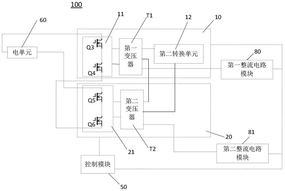
[0021] figure 2 A block diagram of a car charge discharge system according to an embodiment of the present invention, such as figure 2 As shown, the in-vehicle charge discharge system 100 of the embodiment of the present invention includes a first resonant circuit module 10, a second resonance circuit module 20, a first rectifier circuit module 80, a second rectifier circuit module 81, and a control module 50.

[0022] Wherein, the first resonance circuit module 10 is used to conversion processing on the input electrical signal, and the first resonant circuit module 10 includes a first conversion unit 11, a first transformer T1, a second conversion unit 12, wherein in an embodi...


PUM


Abstract

The invention discloses a vehicle-mounted charging and discharging system and a vehicle having the same. The vehicle-mounted charging and discharging system includes a first resonance circuit module, a second resonance circuit module, a first rectification circuit module, a second rectification circuit module and a control module. A resonant circuit module is used to convert the input electrical signal; the second resonant circuit module is used to convert the input electrical signal; the first rectification circuit module and the second rectification circuit module are used to rectify the input electrical signal; A resonant circuit module and the second resonant circuit module multiplex the second conversion unit, and the control module is used to control the first resonant circuit module during the first half cycle of power supply, or to control the second resonant circuit module during the second half cycle of power supply , or, respectively controlling the second conversion unit, the first rectification circuit module, and the second rectification circuit module according to the control timing of the high-voltage battery pack charging the low-voltage battery pack. The system and vehicle can reduce costs and improve stability.

Description

Technical field [0001] The present invention relates to the field of vehicle technology, and more particularly to a vehicle-in-vehicle charger system, and a vehicle having the vehicle charger system. Background technique [0002] figure 1 It is a circuit diagram of a car charger system in the related art that is connected to the grid and the other end is connected to the battery pack, including Part1 'and Part 2' two-stage circuits. When charging is charged, Part1 'achieves AC-DC conversion and power factor correction, output DC voltage. Part2 'is a DC-DC converter, and the output is suitable for charging the battery pack. For this system, in order to provide a smooth input DC voltage, Part1 'and Part 2' require a large capacity of electrolytic capacitance C1 ', increase the volume and cost of the system, and the electrolytic capacitance C1' is a life, and the earthquake shock Question, the reliability of the system is unfavorable. Inventive content [0003] The present inventi...

Claims


Application Information

Patent Timeline
Patent Type & Authority Patents(China)
IPC IPC(8): B60L53/20
CPCB60L53/20B60L2210/10B60L2210/30Y02T10/70Y02T10/72Y02T10/7072Y02T90/14
Inventor 许兴发吴昊刘宇杨柳
Owner BYD CO LTD
Why Eureka
Try Eureka