Flyback switching power supply without electrolytic capacitor, and electronic equipment

A switching power supply circuit, switching power supply technology, applied in electrical components, adjusting electrical variables, output power conversion devices, etc. Problems such as extra static power consumption of switching power supply, to achieve the effect of improving layout space utilization, saving layout space, and reducing economic costs

Pending Publication Date: 2021-04-02
NINGBO SANXING MEDICAL & ELECTRIC CO LTD
View PDF0 Cites 0 Cited by
  • Summary
  • Abstract
  • Description
  • Claims
  • Application Information

AI Technical Summary

Problems solved by technology

[0010] First of all, because the high-voltage electrolytic capacitor CE1 and the high-voltage electrolytic capacitor CE2 with high prices are placed at the rectification rear end of the flyback switching power supply, the economic cost of the entire flyback switching power supply solution is increased;
[0011] Secondly, by connecting multiple high-voltage electrolytic capacitors in series, although the withstand voltage requirements of the flyback switching power supply can be met, it is necessary to add additional parallel resistors for voltage division processing, which brings difficulties to the layout of switching power supply devices;
[0012] Furthermore, due to the leakage current of the high-voltage electrolytic capacitor and the parallel voltage dividing resistor, the additional static power consumption of the flyback switching power supply is increased.

Method used


Image

  • Flyback switching power supply without electrolytic capacitor, and electronic equipment
  • Flyback switching power supply without electrolytic capacitor, and electronic equipment

Examples


Embodiment Construction

[0042] The present invention will be further described in detail below in conjunction with the accompanying drawings and embodiments.

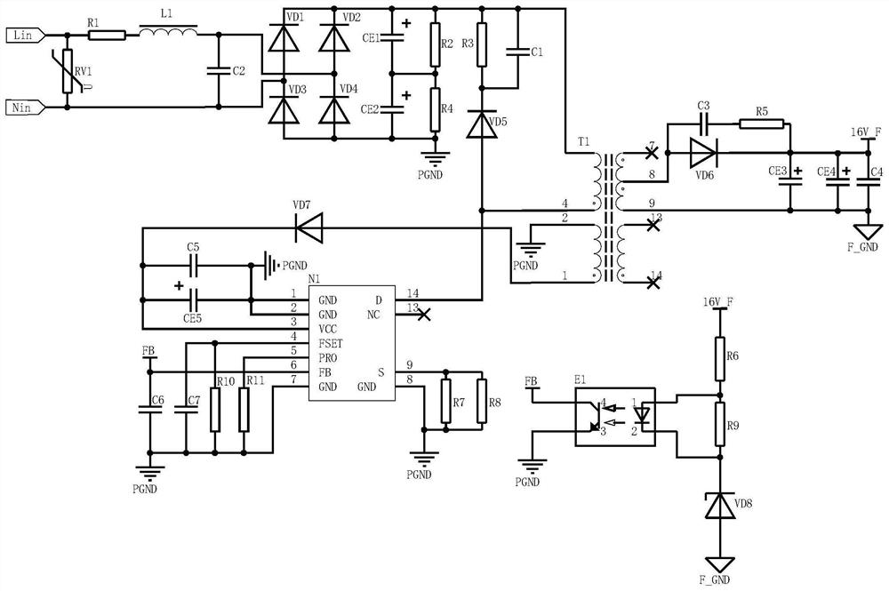
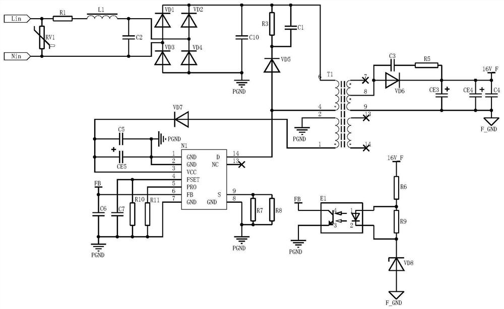
[0043] Such as figure 2 As shown, this embodiment provides a flyback switching power supply without an electrolytic capacitor, including:

[0044] Transient filter circuit;

[0045] The rectifier circuit is connected with the transient filter circuit,

[0046] RCD circuit, connected to the rectification circuit;

[0047] Switching power supply circuit, connected to the RCD circuit;

[0048] The feedback circuit is connected to the switching power supply circuit;

[0049] and an output rectifier circuit;

[0050] Wherein, the rectification circuit has a rectification diode VD1, a rectification diode VD2, a rectification diode VD3, a rectification diode VD4 and a non-electrolytic capacitor C10, the anode of the rectification diode VD1 is connected to the cathode of the rectification diode VD3, the anode of the rectification diode VD2 is conn...


PUM


Abstract

The invention relates to a flyback switching power supply without an electrolytic capacitor, and electronic equipment. The flyback switching power supply comprises a transient filter circuit, a rectification circuit, an RCD circuit, a switching power supply circuit, a feedback circuit and an output rectification circuit, wherein the rectification circuit is provided with four rectification diodesVD1-VD4, and is also provided with an non-electrolytic capacitor C10, the first end of the non-electrolytic capacitor C10 is connected with the negative electrode of the rectification diode VD1 and the negative electrode of the rrectification diode VD2, and the second end of the non-electrolytic capacitor C10 is connected with a power grounding end PGND. According to the invention, a low-cost non-electrolytic capacitor C10 is used for replacing two high-voltage electrolytic capacitors and a parallel resistor, so that the cost of the flyback switching power supply is reduced, and the layout space of switching power supply devices is saved; and because no leakage current exists in the non-electrolytic capacitor C10, a parallel divider resistor does not need to be additionally arranged, and the static power consumption of the flyback switching power supply is reduced.

Description

technical field [0001] The invention relates to the field of flyback switching power supplies, in particular to a flyback switching power supply and electronic equipment without electrolytic capacitors. Background technique [0002] The existing flyback switching power supply has the advantages of efficiently providing multiple DC outputs and meeting the requirements of multiple sets of outputs. see figure 1 As shown, the existing flyback switching power supply includes a transient filter circuit, a rectification circuit, an RCD circuit (also known as an RCD absorption circuit), a switching power supply circuit, a feedback circuit and an output rectification circuit. in: [0003] In the transient filter circuit, when the mains power is connected to the switching power supply Lin and Nin, it first enters the transient filter circuit. The transient filter circuit consists of a piezoresistor RV1, a winding resistor R1, an I-shaped inductor L1 and an X capacitor C2 Compositio...

Claims


Application Information

Patent Timeline
Patent Type & Authority Applications(China)
IPC IPC(8): H02M3/24
CPCH02M3/24
Inventor 俞志根
Owner NINGBO SANXING MEDICAL & ELECTRIC CO LTD
Why Eureka
Try Eureka