
Continuous stamping die for metal stamping

A stamping die and metal stamping technology, applied in the field of stamping die, can solve the problems of affecting the efficiency of stamping, difficult unloading of parts, increase production cost, etc., and achieve the effect of automatic feeding, improving accuracy and saving cost.

Inactive Publication Date: 2021-04-30
柏祝美
View PDF7 Cites 0 Cited by
  • Summary
  • Abstract
  • Description
  • Claims
  • Application Information

AI Technical Summary

Problems solved by technology

[0003] Generally, when performing continuous stamping on metal coils, an independent feeding system is generally used, that is, a set of feeding equipment will be installed outside, which will increase production costs and may also cause stamping accuracy caused by the inability to synchronize feeding and stamping. In general, after the stamping of the coil is completed, the stamping waste will be directly accumulated, which causes the waste to be messy and difficult to clean up, and the stamping cannot continue due to the accumulation of waste, which seriously affects Stamping efficiency, and the general stamped products are collected directly by the receiving plate, but due to the friction of the parts themselves and the friction with the receiving plate, the parts may be stuck on the receiving plate. Cases where accumulation is difficult to unload

Method used


Image

  • Continuous stamping die for metal stamping
  • Continuous stamping die for metal stamping
  • Continuous stamping die for metal stamping

Examples


Embodiment Construction

[0026] In order to make the technical means, creative features, goals and effects achieved by the present invention easy to understand, the present invention will be further described below in conjunction with specific embodiments.

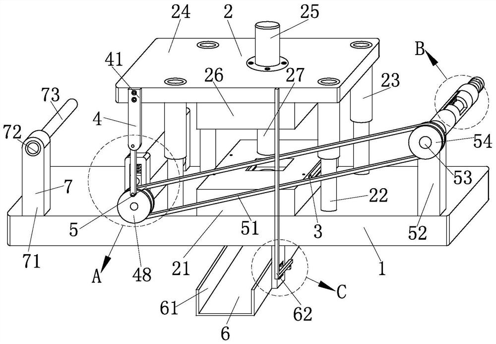
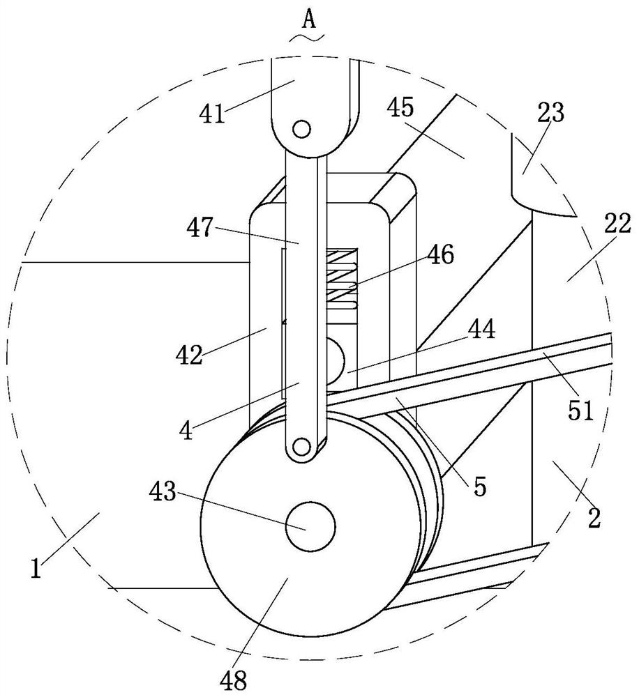
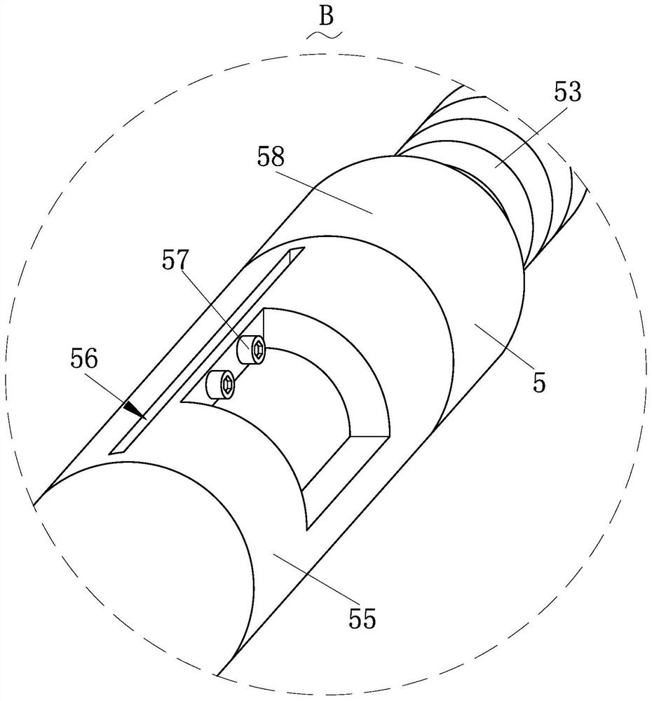
[0027] Such as Figure 1-Figure 7 As shown, a continuous stamping die for metal stamping according to the present invention includes a base 1, a stamping structure 2, a guide conveying structure 3, a feeding structure 4, a waste retracting structure 5, a discharging structure 6 and a discharging structure 7. The stamping structure 2 capable of continuously stamping the metal coil is installed on the top of the base 1 for supporting and installing other parts, and the stamping structure 2 is arranged inside the stamping structure 2 for stamping the metal coil. The guide conveying structure 3 that guides and presses the material; the feeding structure 4 that can rely on the stamping force of the stamping structure 2 to drive the coil for automatic f...


PUM


Abstract

The invention relates to the field of stamping dies, in particular to a continuous stamping die for metal stamping. The continuous stamping die comprises a base, a stamping structure, a guide conveying structure, a feeding structure, a waste winding structure, a discharging structure and a paying-off structure. The stamping structure is installed on a stamping machine to cooperate with the stamping machine in work, and then continuous stamping work on a metal coil can be achieved. The feeding structure can be synchronously driven to work while the stamping structure works, so that stamping and feeding can be synchronously conducted, the feeding accuracy can be improved, automatic feeding can be achieved through the simple structure, the participation of other devices and parts is avoided, and then the effects of saving manpower and saving cost are achieved. The waste winding structure can be synchronously driven to work while the feeding structure conducts automatic feeding, the end of waste can be quickly fixed through the work of the waste winding structure, and then winding is facilitated.

Description

technical field [0001] The invention relates to the field of stamping dies, in particular to a continuous stamping die for metal stamping. Background technique [0002] Mold, various molds and tools used in industrial production for injection molding, blow molding, extrusion, die-casting or forging forming, smelting, stamping and other methods to obtain the required products. In short, a mold is a tool used to make shaped objects. This tool is composed of various parts, and different molds are composed of different parts. It mainly realizes the processing of the shape of the article through the change of the physical state of the formed material. Known as the "Mother of Industry". Stamping die is a special process equipment for processing materials (metal or non-metal) into parts (or semi-finished products) in cold stamping processing, called cold stamping die (commonly known as cold stamping die). Stamping is a pressure processing method that uses a mold installed on a p...

Claims


Application Information

Patent Timeline
Patent Type & Authority Applications(China)
IPC IPC(8): B21D37/10B21D22/02B21D43/00B21D43/09B21D43/22B21D45/08B21C47/04
CPCB21D37/10B21D22/02B21D43/003B21D43/09B21D43/22B21D45/08B21C47/04
Inventor 柏祝美李家浩
Owner 柏祝美
Learn More