Gas turbine engine operable at very low partial load and method of controlling a gas turbine engine

A technology of gas turbine and engine, which is applied in the direction of engine control, gas turbine device, fuel control of turbine/propulsion device, etc., and can solve problems such as fine control incompatibility

Pending Publication Date: 2021-05-18
ANSALDO ENERGIA SWITZERLAND AG
View PDF0 Cites 0 Cited by
  • Summary
  • Abstract
  • Description
  • Claims
  • Application Information

AI Technical Summary

Problems solved by technology

However, the control system needs to cope with a wide range of conditions, and full load operation is rarely compatible with fine control at very low loads
Also, CO emissions are

Method used


Image

  • Gas turbine engine operable at very low partial load and method of controlling a gas turbine engine
  • Gas turbine engine operable at very low partial load and method of controlling a gas turbine engine
  • Gas turbine engine operable at very low partial load and method of controlling a gas turbine engine

Examples


Embodiment Construction

[0026] figure 1 A simplified view of a gas turbine engine generally designated by the numeral 1 is shown. The gas turbine engine 1 comprises a compressor 2 , a first stage combustor 3 , a high pressure turbine 5 , a second stage combustor 7 (also called sequential combustor) and a low pressure turbine 8 .

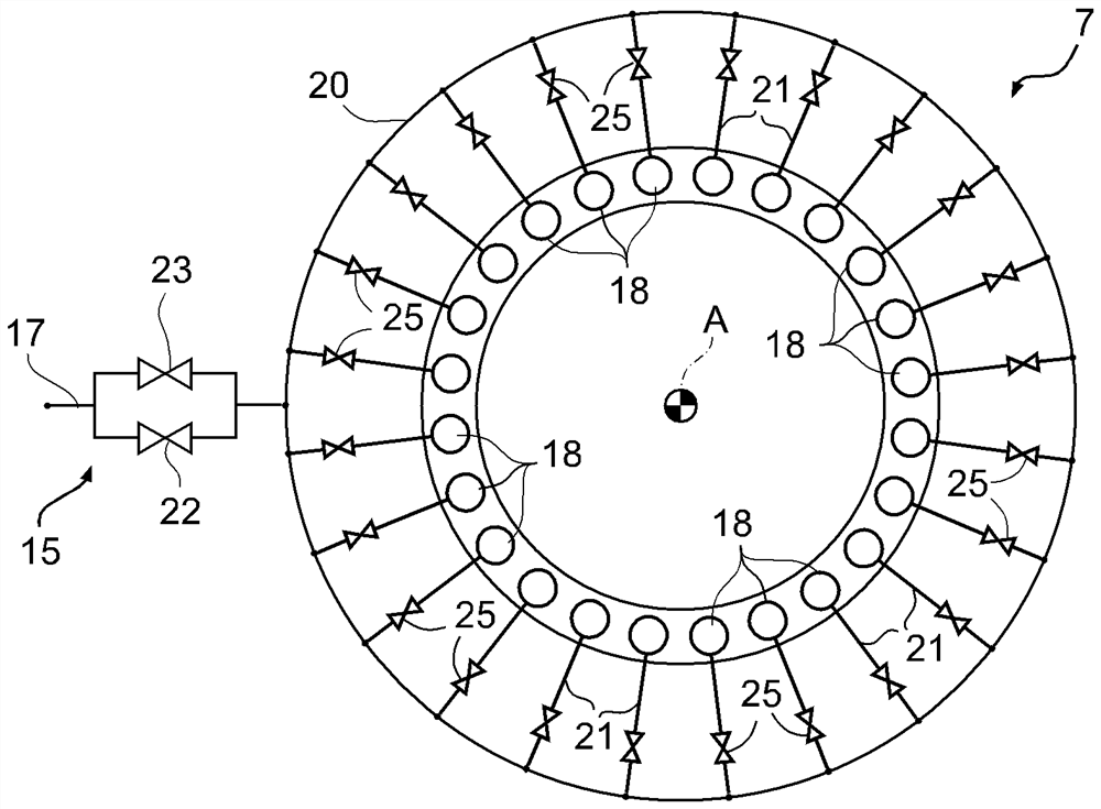
[0027] The fuel supply system 9 delivers fuel flow to operate the first stage burner 3 and the second stage burner 7 .

[0028] A controller 10 receives status signals from system sensors 11 and operates the gas turbine through actuators to provide a controlled power output. The actuators comprise an orientable inlet guide vane 12 of the compressor 2 and a first stage fuel valve system 13 and a second stage fuel valve system 15 of the fuel supply system 9 .

[0029] The compressed air flow supplied by the compressor 2 is increased by a first fuel flow M1 and the air / fuel mixture thus obtained is combusted in a first stage burner 3 . The exhaust gas of the first stage com...


PUM


Abstract

Disclosed is a gas turbine engine comprising a combustor assembly (7), having a plurality of burners (18); a fuel supply system (9), configured to supply a fuel flowrate (M2) to the burners (18) and including a fuel supply line (17) and a main fuel valve (22) between the fuel supply line (17) and the burners (18); and a control unit (10), configured to control the fuel flowrate (M2) using the main fuel valve (22) in a first load range (LR1) from full load to a threshold partial load. The fuel supply system (9) includes an auxiliary fuel valve (23) fluidly coupled between the fuel supply line (17) and at least a group of associated burners (18). The control unit (10) is further configured to control the fuel flowrate (M2) using the auxiliary fuel valve (23) in a second load range (LR2) from the threshold partial load (LTH) to a minimum load (ML).

Description

[0001] Cross References to Related Applications [0002] This patent application claims priority from European Patent Application No. 19209834.1 filed on November 18, 2019, the entire disclosure of which is hereby incorporated by reference. technical field [0003] The present invention relates to a gas turbine engine operable at very low part loads and to a method of controlling the gas turbine engine. Background technique [0004] It is well known that controlling pollutant emissions is a first and foremost objective in the design of any type of heat engine and especially gas turbines for power plants. In fact, awareness of environmental risks has prompted regulations with increasingly stringent requirements. On the other hand, the organization and changing demands of modern electricity markets do not allow power stations to be operated under constant load conditions. In contrast, very flexible operation is required to meet demand fluctuations (including sudden rises or ...

Claims


Application Information

Patent Timeline
IPC IPC(8): F02C9/26F02C7/232F23R3/28
CPCF02C7/232F02C9/26F23R3/28F02C6/003F02C7/222F02C7/228F02C9/263F05D2270/08F05D2270/11F05D2270/306F05D2270/31F23N2235/18F23K2300/206F23K2400/201
Inventor J·里恩R·雅科比R·凯勒尔A·斯图德鲁斯D·布里C·阿佩尔
Owner ANSALDO ENERGIA SWITZERLAND AG
Why Eureka
Try Eureka