
Dynamic composite loading incident bar

A technology of compound loading and incident rod, which is applied in the direction of testing the strength of materials, measuring devices, and instruments using one-time impact force, can solve the problems of overall complexity of the device, inconvenient implementation, and difficulty in synchronous triggering of compression waves and torsional waves, etc., and achieve reduction The effect of complexity, simple structure and convenient implementation

Active Publication Date: 2021-06-15
SUN YAT SEN UNIV
View PDF8 Cites 1 Cited by
  • Summary
  • Abstract
  • Description
  • Claims
  • Application Information

AI Technical Summary

Problems solved by technology

[0003] The current separated Hopkinson bar device includes compression bar, tie bar and torsion bar, which are only suitable for single load loading and cannot realize combined loading tests (such as tension-torsion, compression-torsion combined loading)
Part of the separated Hopkinson bar device with composite loading function is mainly realized by adding a torque loader, but this kind of realization method, the overall complexity of the device, difficulty in synchronous triggering of compression waves and torsional waves, and inconvenient implementation

Method used


Image

  • Dynamic composite loading incident bar
  • Dynamic composite loading incident bar
  • Dynamic composite loading incident bar

Examples


Embodiment Construction

[0021] The following will clearly and completely describe the technical solutions of the embodiments of the present application with reference to the accompanying drawings. Apparently, the described embodiments are part of the embodiments of the present application, not all of them. Based on the embodiments in the embodiments of the present application, all other embodiments obtained by persons of ordinary skill in the art without making creative efforts belong to the protection scope of the embodiments of the present application.

[0022] In the description of the embodiments of the present application, it should be noted that the terms "center", "upper", "lower", "left", "right", "vertical", "horizontal", "inner", "outer " and other indicated orientations or positional relationships are based on the orientations or positional relationships shown in the drawings, and are only for the convenience of describing the embodiments of the present application and simplifying the descr...


PUM


Abstract

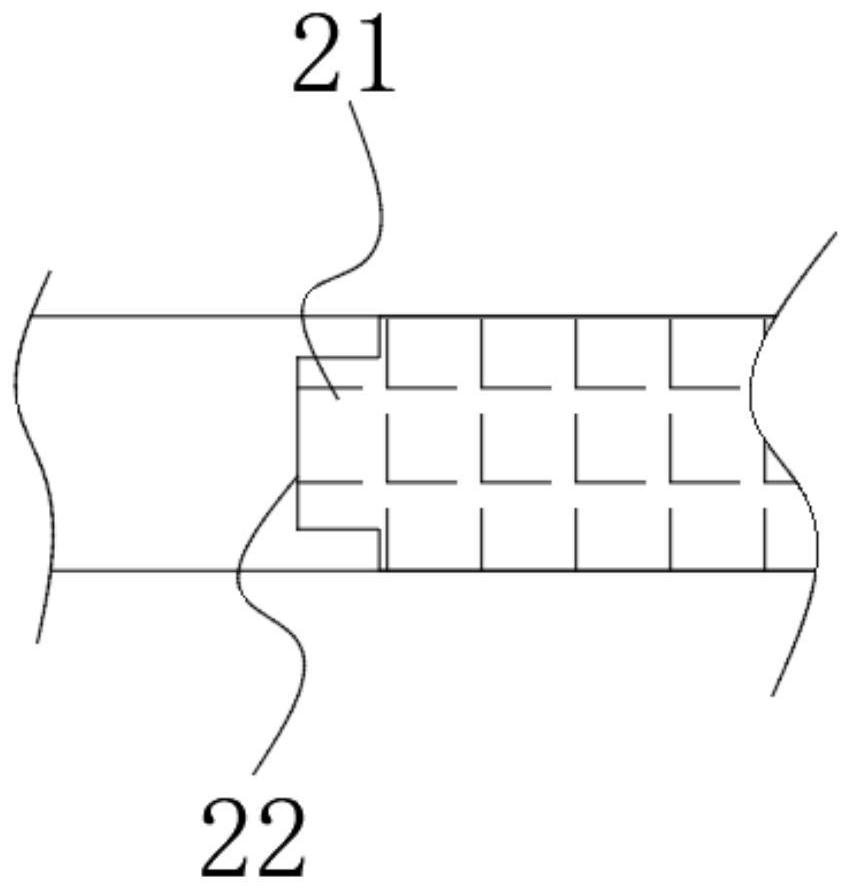
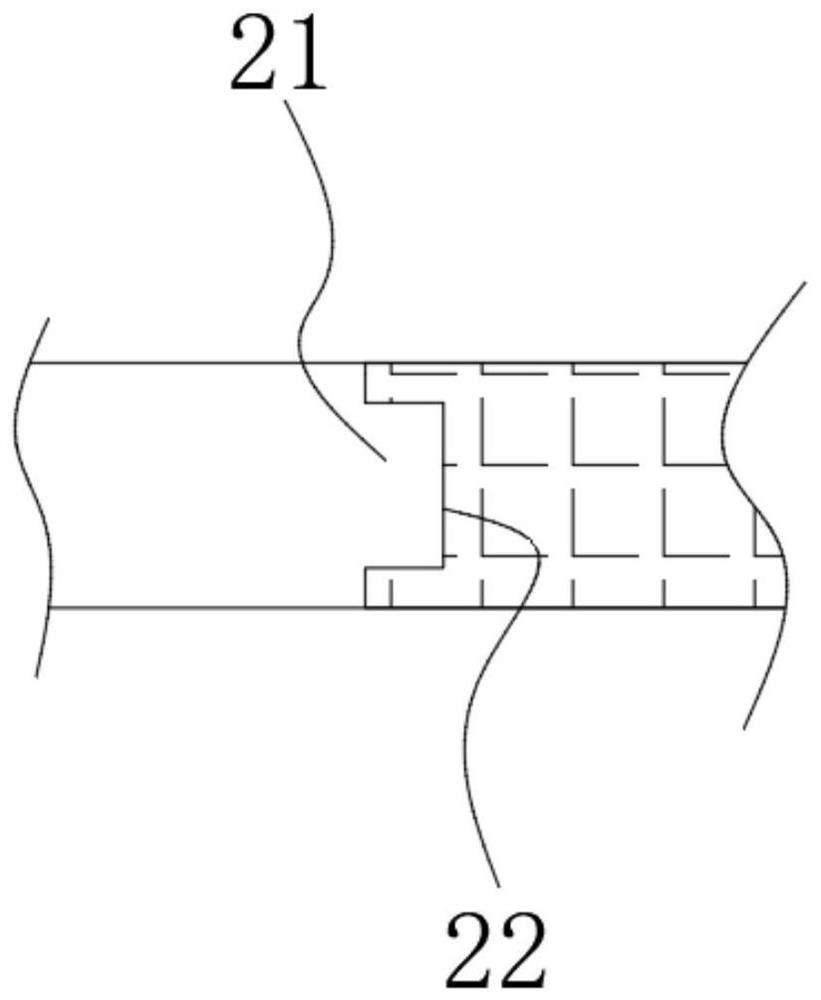
The invention discloses a dynamic composite loading incident bar, which comprises a first bar section, a second bar section and a compression-torsion metamaterial section, wherein the first rod section, the compression-torsion metamaterial section and the second rod section are sequentially arranged in the same axis direction; and one end of the compression-torsion metamaterial section is connected with one end of the first rod section, and the other end is connected with one end of the second rod section. The compression / stretching waves can be converted into compression-torsion / tension-torsion composite waves by utilizing the compression-torsion metamaterial section, and when the first rod section is impacted, the second rod section can output a compression / stretching and torsion composite load through the compression-torsion metamaterial section, so that the composite loading test requirement can be met. According to the structural improvement, the metamaterial is creatively combined and applied to the incident bar, so that the improved incident bar has a composite loading function. Compared with an existing composite loading implementation mode, the compression / stretching waves and torsion waves are generated on the second rod section at the same time, and the problem of synchronous triggering does not exist; and the structure is simple, and the complexity of the device is greatly reduced.

Description

technical field [0001] The present application relates to the technical field of material dynamic experiments, in particular to an incident rod with dynamic composite loading. Background technique [0002] In a series of practical problems in a wide range of fields such as engineering technology, military technology, scientific research, and even daily life, people will encounter various explosion / shock load problems, and can observe objects in explosion / shock loads. The mechanical response under impact loads is significantly different from that under static loads. High strain rate deformation is one of the main characteristics of material response, therefore, understanding the mechanical response of materials at high strain rates will greatly help the engineering applications and engineering design of these materials. At present, the separated Hopkinson bar is the most widely used experimental device for testing the mechanical properties of materials under high strain rate...

Claims


Application Information

Patent Timeline
Patent Type & Authority Applications(China)
IPC IPC(8): G01N3/30
CPCG01N3/30G01N2203/001G01N2203/0026
Inventor 胡玲玲殷秋运
Owner SUN YAT SEN UNIV
Learn More