Jean clothing hole breaking equipment

A clothing and hole-breaking technology, applied in textile and papermaking, fabric surface trimming, thorn patterns, etc., can solve the problems such as the inability to automatically clamp denim clothing, the inability to automatically transport denim clothing, and the inability to precisely pierce denim clothing.

Active Publication Date: 2021-06-25
浙江万联服饰有限公司
View PDF6 Cites 0 Cited by
  • Summary
  • Abstract
  • Description
  • Claims
  • Application Information

AI Technical Summary

Problems solved by technology

[0005] In order to overcome the shortcomings of traditional hole-breaking equipment that cannot realize automatic clamping of denim garments, automatic delivery of denim garments, and inability to accurately break holes in denim garments, the technical problem of the present invention is to provide a device that can automatically clamp denim garments and automatically transport denim garments. Denim clothing hole-punching equipment for precise holes in denim clothing

Method used


Image

  • Jean clothing hole breaking equipment
  • Jean clothing hole breaking equipment
  • Jean clothing hole breaking equipment

Examples


Embodiment 1

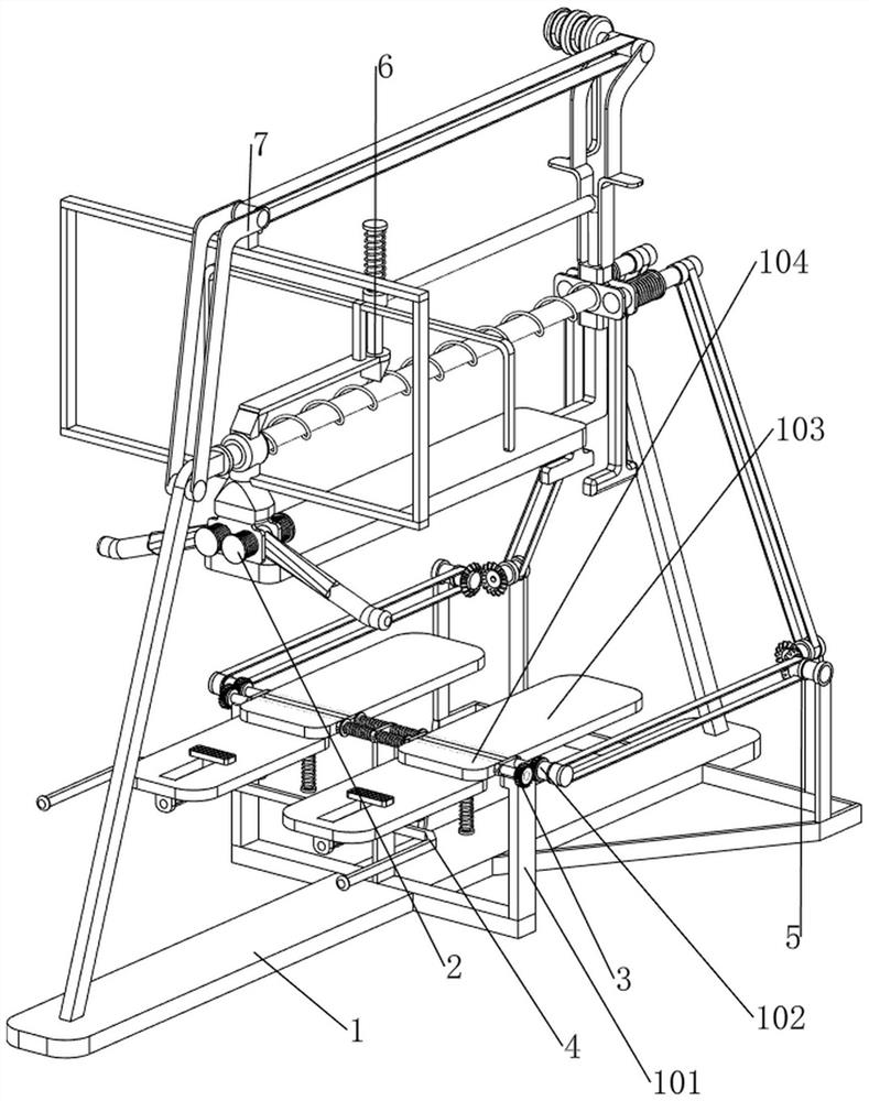
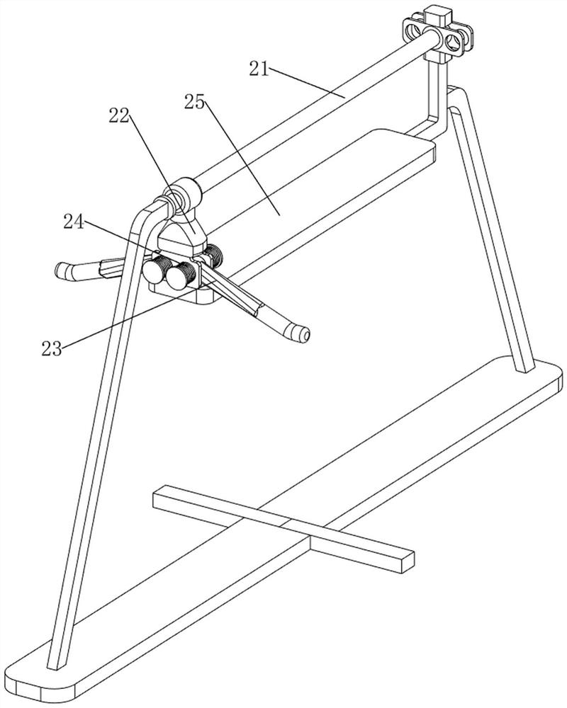
[0065] A denim clothing hole device, such as Figure 1-Figure 3 As shown, it includes a base plate 1, a rotating support rod 101, a first rotating shaft 102, a first rotating clamping plate 103, a second rotating clamping plate 104, a clothes putting mechanism 2 and a rotating clamping mechanism 3, and the upper, middle, left and right sides of the base plate 1 Rotating support rods 101 are arranged on both sides, and the first rotating shaft 102 is rotationally connected between the upper parts of the two rotating supporting rods 101. The number of the first rotating shafts 102 is two. The clamping plate 103 is provided with a second rotating clamping plate 104 on the first rotating shaft 102 on the front side, the clothes putting mechanism 2 is provided on the bottom plate 1 , and the rotating clamping mechanism 3 is provided on the rotating support rod 101 .

[0066] When people want to break copper on denim clothing, they can use this denim clothing hole-breaking device. F...

Embodiment 2

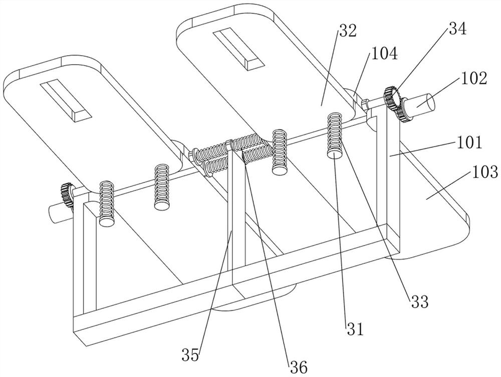
[0072] On the basis of Example 1, such as Figure 4-Figure 7 As shown, a hole scraping mechanism 4 is also included, and a hole scraping mechanism 4 is provided between the two second rotating clamping plates 104. The hole scraping mechanism 4 includes a first sliding sleeve 41, a sliding scraper 42 and a second spring 43 , the front sides of the bottoms of the two second rotating clamping plates 104 are provided with a first sliding sleeve 41, and a sliding scraper 42 is slidably connected between the two first sliding sleeves 41, and the left and right sides of the sliding scraper 42 are wound with The second spring 43 is connected to the first sliding sleeve 41 and the sliding scraper 42 at both ends of the second spring 43 respectively.

[0073] After the jeans are clamped by the first rotating clamping plate 103 and the second rotating clamping plate 104, when the second rotating clamping plate 104 is turned to a vertical angle, the user pulls the sliding scraper 42 upwar...


PUM


Abstract

The invention relates to hole breaking equipment, in particular to jean clothing hole breaking equipment. The invention provides the jean clothing hole breaking equipment which can automatically clamp jean clothing, automatically convey the jean clothing and accurately break holes in the jean clothing. The jean clothing hole breaking equipment comprises a bottom plate, first rotating shafts and first rotary clamping plates; rotary supporting rods are arranged on the two sides of the upper middle portion of the bottom plate; the first rotating shafts are rotatably connected between the upper parts of the two rotary supporting rods, and the number of the first rotating shafts is two; and the first rotary clamping plates are arranged on the first rotating shafts. According to the equipment, second rotary clamping plates drive second sliding connecting rods, sliding clamping plates and first springs to rotate, so that jeans are clamped by the first rotary clamping plates and the second rotary clamping plates, and the effect that the jeans are clamped by the first rotary clamping plates and the second rotary clamping plates is achieved.

Description

technical field [0001] The invention relates to a hole-punching device, in particular to a denim clothing hole-punching device. Background technique [0002] Young people's pursuit of clothing is developing towards fashion. In recent years, some young people like to wear denim clothing with holes to reflect their unique characters. Low, and the warp and weft of the polished trousers will be completely broken, and the dense line effect that can not only have the effect of holes but also leave the weft can not be achieved. [0003] Patent application CN206986525U, with a publication date of 20180209, discloses a denim clothing hole-punching device, including a grinding table, a box body, a grinding device, a fixed block, a fixed frame, a drive motor, a support frame, a lifting device and a cover plate, etc., start The drive motor drives the grinding device to run, and the user puts the denim on the lifting device, and the lifting device transports the denim to the grinding ta...

Claims


Application Information

Patent Timeline
Patent Type & Authority Applications(China)
IPC IPC(8): D06C23/00
CPCD06C23/00Y02W30/66
Inventor 陈富华
Owner 浙江万联服饰有限公司
Why Eureka
Try Eureka