
Power distribution box with cable clamping mechanism

A technology of clamping mechanism and distribution box, which is applied in the direction of electrical components, substation/switch layout details, etc., and can solve problems such as inability to perform cable clamping operations

Active Publication Date: 2021-06-25
山东万盛电气有限公司
View PDF5 Cites 2 Cited by
  • Summary
  • Abstract
  • Description
  • Claims
  • Application Information

AI Technical Summary

Problems solved by technology

[0003] The purpose of the present invention is to provide a distribution box with a cable clamping mechanism to solve the problem that the cable clamping operation cannot be performed in the above-mentioned background technology

Method used


Image

  • Power distribution box with cable clamping mechanism
  • Power distribution box with cable clamping mechanism
  • Power distribution box with cable clamping mechanism

Examples


Embodiment Construction

[0024] The following will clearly and completely describe the technical solutions in the embodiments of the present invention with reference to the accompanying drawings in the embodiments of the present invention. Obviously, the described embodiments are only some of the embodiments of the present invention, not all of them. The components of the embodiments of the invention generally described and illustrated in the figures herein may be arranged and designed in a variety of different configurations. Accordingly, the following detailed description of the embodiments of the invention provided in the accompanying drawings is not intended to limit the scope of the claimed invention, but merely represents selected embodiments of the invention. Based on the embodiments of the present invention, all other embodiments obtained by those skilled in the art without making creative efforts belong to the protection scope of the present invention.

[0025] Below, refer to Figure 1 to F...


PUM


Abstract

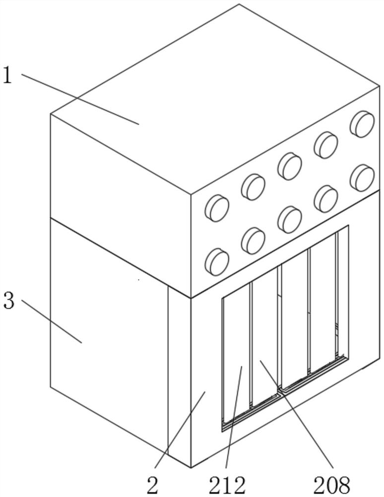
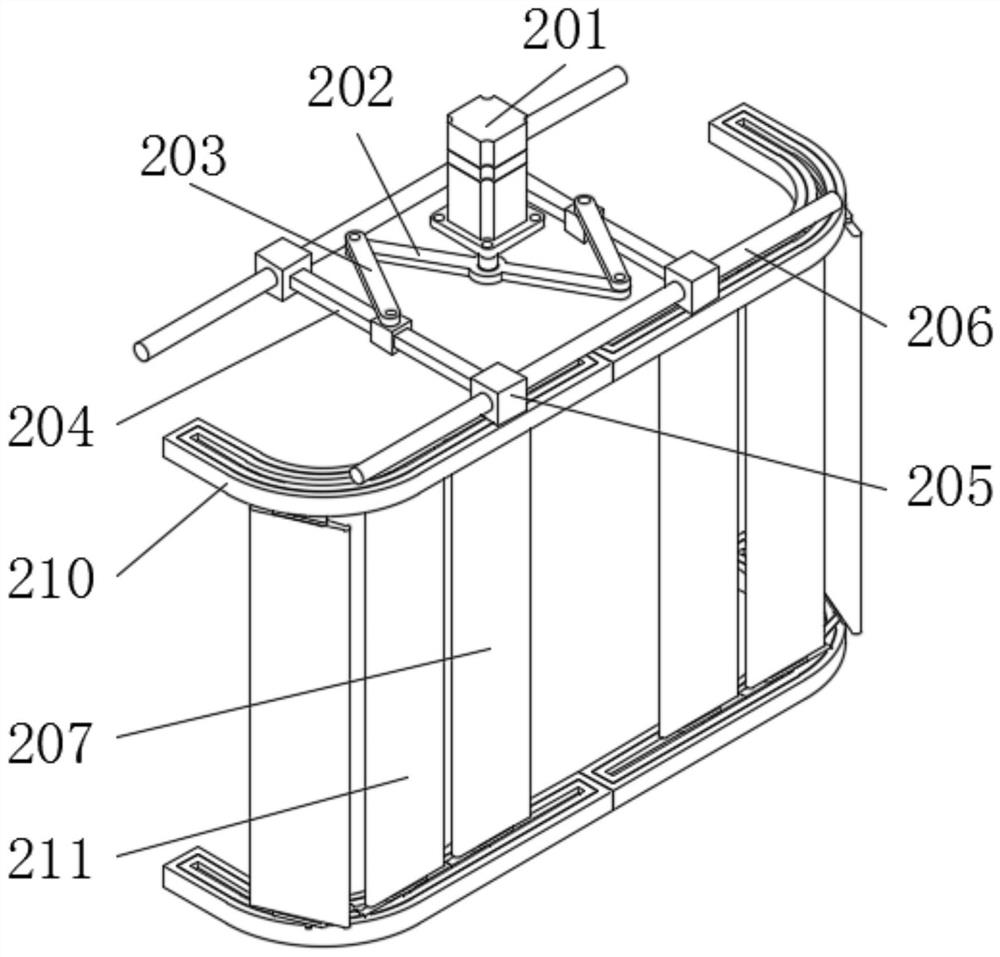
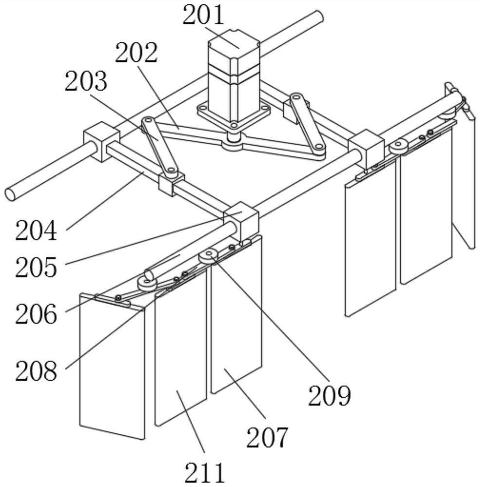
The invention discloses a power distribution box with a cable clamping mechanism. The power distribution box comprises a display box, wherein the bottom end of the display box is fixedly connected with an opening and closing mechanism which is in the same vertical plane with the side wall of the display box and is of a concentric-square-shaped structure, and the side wall of the opening and closing mechanism is located at the bottom end of the display box and is fixedly connected with a cabinet body. According to the power distribution box with the cable clamping mechanism, by arranging clamping sliding plates, in clamping plates, clamping buttons drive clamping control rods to move, the clamping control rods drive pushing blocks to slide along the inner walls of the clamping plates, the pushing blocks move to drive connecting rods to move, the connecting rods drive the clamping sliding plates to slide along the inner walls of the clamping plates through clamping springs, the sliding length of the clamping sliding plate is equal to the length of the connecting rod, the central axis of the pushing block, the middle points of the two sets of connecting rods and the central axis of the clamping groove coincide, and clamping operation on the cable is achieved through relative movement of the clamping sliding plate and the clamping groove.

Description

technical field [0001] The invention relates to the technical field of distribution boxes, in particular to a distribution box with a cable clamping mechanism. Background technique [0002] A distribution box is a box in which electrical appliances and their circuits are placed to distribute electrical energy. Collectively referred to as the power distribution center. They are centrally installed in fixed locations and distribute electrical energy to lower-level power distribution equipment in different locations. However, the existing distribution box has the problem of being unable to perform cable clamping operations during use, resulting in messy cables and unsightly appearance. The efficiency of maintenance and testing of the distribution box is low and cannot meet people's needs. Contents of the invention [0003] The object of the present invention is to provide a distribution box with a cable clamping mechanism, so as to solve the problem that the cable clamping ...

Claims


Application Information

Patent Timeline
Patent Type & Authority Applications(China)
IPC IPC(8): H02B1/46H02B1/38H02B1/36H02B1/48H02G3/30
CPCH02B1/46H02B1/38H02B1/36H02B1/48H02G3/30
Inventor 闻杨根
Owner 山东万盛电气有限公司
Learn More