Temperature drift calibration method for high-precision low-temperature drift temperature measurement circuit of infrared detector

A technology of infrared detector and calibration method, which is applied in the field of aerospace optical remote sensors, can solve problems such as temperature drift compensation effect verification, and achieve the effect of simple algorithm, avoiding high cost, and easy realization

Active Publication Date: 2021-08-13
BEIJING RES INST OF SPATIAL MECHANICAL & ELECTRICAL TECH
View PDF6 Cites 0 Cited by
  • Summary
  • Abstract
  • Description
  • Claims
  • Application Information

AI Technical Summary

Problems solved by technology

The invention can solve the problems of temperature drift calibration and temperature drift compensation effect verification of high precision low temperature drift temperature measuring circuit

Method used


Image

  • Temperature drift calibration method for high-precision low-temperature drift temperature measurement circuit of infrared detector
  • Temperature drift calibration method for high-precision low-temperature drift temperature measurement circuit of infrared detector
  • Temperature drift calibration method for high-precision low-temperature drift temperature measurement circuit of infrared detector

Examples


Embodiment

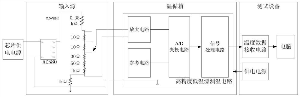
[0040] The temperature drift calibration system includes: signal analog input source, high-precision temperature measurement control circuit, temperature cycle box, test equipment and connecting cables. The high-precision temperature measurement control circuit includes: amplifying circuit, reference circuit, A / D acquisition unit and data receiving and processing unit. Signal analog input sources include: chip power supply, voltage source reference chip, precision resistors;

[0041] 1) Connect the signal analog input source, high-precision temperature measurement control circuit, and test equipment in sequence through the connecting cable figure 1 connection; the high-precision temperature measurement control circuit is placed inside the temperature cycle box; the temperature cycle box is used to adjust the temperature of the high-precision temperature measurement control circuit. The high-precision temperature measurement control circuit includes: an amplification circuit a...


PUM


Abstract

The invention discloses a temperature drift calibration method for a high-precision low-temperature drift temperature measurement circuit of an infrared detector. The temperature drift calibration method comprises the steps of sequentially connecting a signal simulation input source, a high-precision temperature measurement control circuit and test equipment through connecting cables; establishing a temperature drift proportion relation table of an amplifying circuit and a reference circuit under different input gears of the input source; and performing linear interpolation on the temperature drift proportional relation table to obtain a compensation relation table of one digital quantity changed by the amplifying circuit and the variable quantity of the reference circuit, and performing temperature drift compensation processing on a digital temperature signal output by the amplifying circuit. The method is used for calibrating the relation between the amplifying circuit, the reference circuit and the environment temperature in the high-precision low-temperature-drift temperature measurement circuit of the infrared detector, and establishing the temperature drift change relation between the amplifying circuit and the reference circuit.

Description

technical field [0001] The invention belongs to the technical field of aerospace optical remote sensors, and relates to a temperature drift calibration method for a high-precision low-temperature drift focal plane temperature measurement circuit, which can be used for temperature drift calibration and temperature drift compensation effect verification of the high-precision focal plane temperature measurement circuit. Background technique [0002] In the field of space remote sensing imaging, low temperature environment is an important part of infrared detectors. [0003] As the infrared remote sensing spectrum becomes longer and longer, the temperature of the infrared MCT detector is required to be lower and lower, and the temperature stability is higher and higher. At present, the temperature control accuracy of the focal plane of the long-wave MCT detector is required to reach 0.01°C. At present, the traditional temperature measurement method does not have a temperature dr...

Claims


Application Information

Patent Timeline
Patent Type & Authority Applications(China)
IPC IPC(8): G01J5/28G01J5/10G01J5/00
CPCG01J5/28G01J5/10G01J5/00G01J2005/0077G01J5/80
Inventor 金占雷徐丽娜原娜许云飞张婷婷
Owner BEIJING RES INST OF SPATIAL MECHANICAL & ELECTRICAL TECH
Why Eureka
Try Eureka