Flue gas recirculation system of household garbage incineration power plant

A domestic waste incineration and recycling system technology, applied in the direction of incinerators, combustion types, combustion equipment, etc., can solve problems such as increased costs, inability to meet flue gas, and increased incomplete combustion

Pending Publication Date: 2021-08-20
CHINA TIANYING +1
View PDF3 Cites 3 Cited by
  • Summary
  • Abstract
  • Description
  • Claims
  • Application Information

AI Technical Summary

Problems solved by technology

This patent has the following defects: 1) The primary air is sucked from the garbage pit in front of the furnace to be heated by the heating surface at the tail, and then sent back to the front of the furnace. The flue gas recirculation pipe at the tail is connected to the primary air inlet pipe in front of the furnace. The pipe is too long and the overall arrangement complex
The defects of this patent are: 1) The air replenished from the exhaust duct is cold air, which will affect the temperature distribution of the furnace when the air volume is large, which may lead to insufficient combustion and cannot meet the flue gas 850°C / 2s requirements
This patent has the following defects: the oxygen content in the flue gas is low, and when the primary air or secondary air is completely replaced by the recirculated flue gas volume, in order to ensure the discharge of CO, the recirculated flue gas volume must be increased, but a large amount of Flue gas will lead to lower combustion temperature and increased incomplete combustion
[0007] From the above, we can see that the current flue gas recirculation technology in domestic waste incineration power plants mainly has the following problems: 1. The complete combination of the primary and secondary air ducts and the flue gas recirculation piping system results in lengthy piping arrangements; 2. Supplementary air It is cold air, which affects the temperature distribution of the furnace; 3. The introduction of air alone requires an additional fan, which increases the cost; 4. Completely replace the primary or secondary air with the amount of recirculated flue gas, which may lead to incomplete combustion

Method used


Image

  • Flue gas recirculation system of household garbage incineration power plant

Examples


Embodiment Construction

[0025] In order to explain in detail the technical solutions adopted by the present invention to achieve the intended technical purpose, the technical solutions in the embodiments of the present invention will be clearly and completely described below in conjunction with the drawings in the embodiments of the present invention. Obviously, the described implementation Examples are only part of the embodiments of the present invention, rather than all embodiments, and, on the premise of not paying creative work, the technical means or technical features in the embodiments of the present invention can be replaced, the following will refer to the accompanying drawings and combine Examples illustrate the present invention in detail.

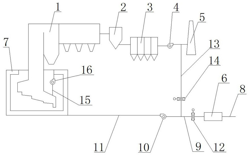
[0026] Such as figure 1 As shown, a flue gas recirculation system of a domestic waste incineration power plant of the present invention includes an incinerator 1, a reaction tower 2, a dust collector 3, an induced draft fan 4, a chimney 5 and an air p...


PUM


Abstract

The invention discloses a flue gas recirculation system of a household garbage incineration power plant. The flue gas recirculation system comprises an incinerator, a reaction tower, a dust remover, an induced draft fan, a chimney and an air preheater, a flue gas outlet of the incinerator is connected with an inlet of the reaction tower, an outlet of the reaction tower is connected with one end of the dust remover, and the other end of the dust remover is connected with one end of the induced draft fan. The other end of the induced draft fan is connected with the chimney, air is introduced into one end of the air preheater, and the other end of the air preheater and the other end of the induced draft fan are connected with a secondary air chamber of the incinerator. According to the flue gas recirculation system of the household garbage incineration power plant, recycled flue gas replaces part of secondary air, so that the content of inert gas in a combustion area is increased, the flue gas absorbs heat, the concentration of oxygen is reduced, the flue gas and combustion-supporting air spread and combust in a high-temperature and low-oxygen atmosphere, the flame volume is multiplied, a local high-temperature area is reduced, temperature distribution is more uniform, generation of thermal NOx is inhibited, the coking problem of a hearth can be solved, and the heat efficiency and the generating capacity are improved.

Description

technical field [0001] The invention relates to a flue gas recirculation system, in particular to a flue gas recirculation system of a domestic waste incineration power plant, which belongs to the field of waste incineration treatment. Background technique [0002] With the improvement of economic level, the development of waste incineration power generation industry is conducive to resource reuse, harmlessness, energy saving and many other advantages, and has been promoted and developed by many countries in the world. At present, some developed countries have relatively advanced technology, which can efficiently treat the flue gas produced by incineration, reduce the emission of pollutants, and even achieve zero pollution. At present, the technology of domestic waste incineration power plants is not perfect, and there are common serious coking, high frequency of shutdown and ash cleaning; unstable combustion, large fluctuations in the temperature of the first flue, affectin...

Claims


Application Information

Patent Timeline
Patent Type & Authority Applications(China)
IPC IPC(8): F23G5/44F23L15/00F23L9/00F23J15/00F23J15/02
CPCF23G5/44F23J15/006F23J15/02F23J2215/20F23J2217/101F23L9/00F23L15/00Y02E20/12Y02E20/34
Inventor 姜杭杰李军李阳顾春华李少杰林蒙王允旭
Owner CHINA TIANYING
Why Eureka
Try Eureka