Eureka AIR delivers breakthrough ideas for toughest innovation challenges, trusted by R&D personnel around the world.

Coil winding device and control method thereof

A winding device and coil technology, used in coil manufacturing, inductance/transformer/magnet manufacturing, electrical components, etc., can solve the problems of coil skeleton pressure skeleton damage, stuck, inaccurate number of coil turns, etc., to solve the problem of coil winding The number of coils is inaccurate, avoiding the sticking and slipping of the winding action, and improving the effect of space utilization

Active Publication Date: 2021-11-12
NINGBO CRRC TIMES TRANSDUCER TECH CO LTD
View PDF0 Cites 0 Cited by
  • Summary
  • Abstract
  • Description
  • Claims
  • Application Information

AI Technical Summary

Problems solved by technology

[0003] At present, the conventional equipment on the market cannot meet the winding requirements of series multi-coils, mainly because the structural design of series multi-coils will lead to the following problems in the winding process: 1. Due to the irregular shape of the injection molding product of the coil skeleton, it will cause During the winding process, problems such as stagnation and wire jumping occurred; 2. Slipping occurred due to insufficient fixation of the coil skeleton; 3. Product function problems were caused by irregular wiring and inaccurate coil turns; 4. Skeleton damage or detachment caused by too much or too little pressure

Method used


Image

  • Coil winding device and control method thereof
  • Coil winding device and control method thereof
  • Coil winding device and control method thereof

Examples


Embodiment 1

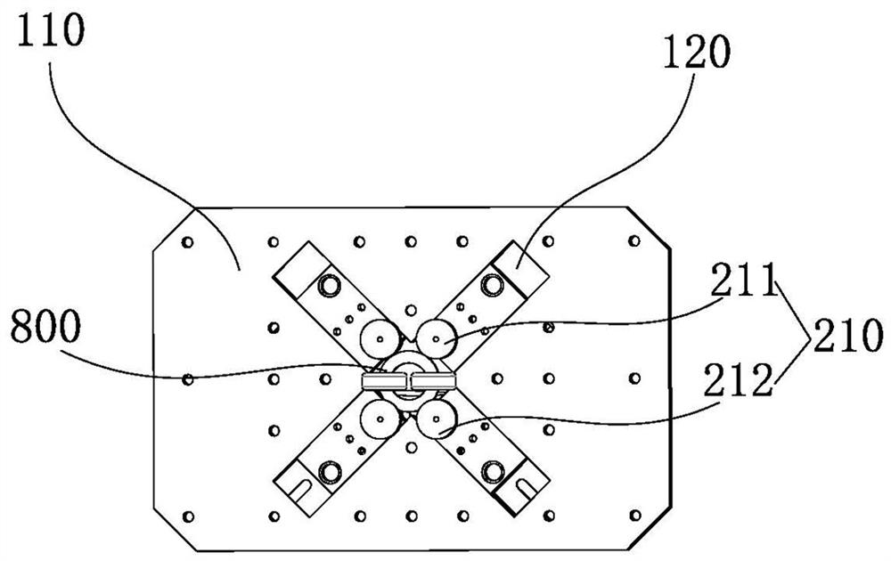
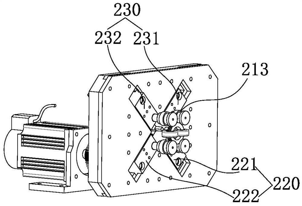
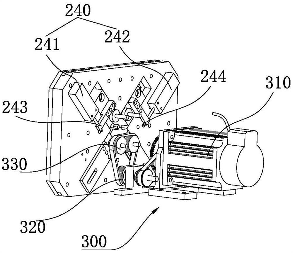
[0054] Such as Figure 1 to Figure 7 As shown, the invention provides a coil winding device, comprising:

[0055] Body 100, and a support plate 110 is provided on the body 100, wherein, the support plate 110 is provided with a vertically arranged line inlet channel 130; the drive mechanism 300 is installed on the body 100, and the output end of the drive mechanism 300 is set There are two driving wheels 212 rotating in the same direction; the sliding mechanism 200 is installed on the support plate 110, and the output end of the sliding mechanism 200 is provided with two driven wheels 211 rotating in the same direction, wherein the driven wheel 211 and the driving wheel The wheel 212 is arranged up and down along the wire-feeding direction of the wire-feed channel 130, and the space between the driven wheel 211 and the driving wheel 212 is used as the clamping space of the skeleton 800 to be wound; The frame 800 is clamped between the driven wheel 211 and the driving wheel 212...

Embodiment 2

[0079] Such as Figure 8 As shown, the present invention also provides a coil winding control method, comprising steps:

[0080] S1: Turn on the power and initialize the device;

[0081] S2: Start the first switch, the first sliding cylinder drives the first sliding plate to move through the first connecting piece, and the second sliding cylinder drives the second sliding plate to move through the second connecting piece, so that the two driven wheels move away from the driving wheel The direction of movement, and the distance between the two driven wheels gradually increases;

[0082] S3: Put the winding skeleton between the two driving wheels and the two driven wheels, and adjust the position;

[0083] S4: Turn off the first switch, the first sliding cylinder drives the first sliding plate to move through the first connecting piece, and the second sliding cylinder drives the second sliding plate to move through the second connecting piece, so that the two driven wheels are...

Embodiment 3

[0087] Such as Figure 9 As shown, the present invention also provides a coil winding control method, comprising steps:

[0088] S1: Turn on the power and initialize the device;

[0089] S2: Start the first switch, the first sliding cylinder drives the first sliding plate to move through the first connecting piece, and the second sliding cylinder drives the second sliding plate to move through the second connecting piece, so that the two driven wheels move away from the driving wheel The direction of movement, and the distance between the two driven wheels gradually increases;

[0090] S3: Put the winding skeleton between the two driving wheels and the two driven wheels, and adjust the position;

[0091] S4: Turn off the first switch, the first sliding cylinder drives the first sliding plate to move through the first connecting piece, and the second sliding cylinder drives the second sliding plate to move through the second connecting piece, so that the two driven wheels are...


PUM


Abstract

The invention provides a coil winding device and a control method thereof, belonging to the technical field of coil production equipment, comprising a body, and a support plate is arranged on the body; a driving mechanism is installed on the body, and an output end of the driving mechanism is provided with Two driving wheels that rotate in the same direction; the sliding mechanism is installed on the support plate, and the output end of the sliding mechanism is provided with two driven wheels that rotate in the same direction. Line direction is set up and down. The present invention provides a coil winding device and a control method thereof. By setting a driving mechanism and a sliding mechanism, the driving wheel and the driven wheel can not only drive the bobbin to be wound for rotating winding, but also can be tightly wound during the winding process. Fitting to the bobbin, keeping the bobbin stable, avoiding the problems of sticking and slipping of the winding action caused by the irregular shape of the bobbin to be wound or the unsteady pressing, and solving the problem of inaccurate number of coil windings, greatly improving the Availability of equipment.

Description

technical field [0001] The invention belongs to the technical field of coil production equipment, and in particular relates to a coil winding device and a control method thereof. Background technique [0002] The coil is used as an electromagnetic induction element in the field of sensor measurement. The conventional use is to use a single coil as an induction element. In order to meet the requirements of higher detection accuracy, a serial multi-coil is used as an electromagnetic induction module. Compared with a single coil Said that the detection accuracy is higher, the response is more sensitive, and the range coverage is wider, which has become a new generation of development requirements. [0003] At present, the conventional equipment on the market cannot meet the winding requirements of series multi-coils, mainly because the structural design of series multi-coils will cause the following problems in the winding process: 1. Due to the irregular shape of the coil skel...

Claims


Application Information

Patent Timeline
Patent Type & Authority Patents(China)
IPC IPC(8): H01F41/06H01F41/082H01F41/096H01F41/094
CPCH01F41/06H01F41/082H01F41/096H01F41/094
Inventor 刘建军闫秋菊朱俊达洪振惠彭乐观陈双喜梁倩倩
Owner NINGBO CRRC TIMES TRANSDUCER TECH CO LTD
Why Eureka
Eureka Blog
Learn More