
Drill

A drill and drill tip technology, applied in the field of drills, can solve problems such as increasing the feed rate, and achieve the effect of consistent outreach

Pending Publication Date: 2021-09-28
KENNAMETAL INC
View PDF1 Cites 0 Cited by
  • Summary
  • Abstract
  • Description
  • Claims
  • Application Information

AI Technical Summary

Problems solved by technology

A portion of the torque is distributed from the main cutting edge to the auxiliary cutting edge, whereby it is possible to increase the feed rate

Method used


Image

  • Drill
  • Drill
  • Drill

Examples


Embodiment Construction

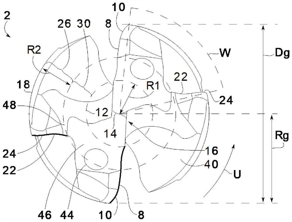
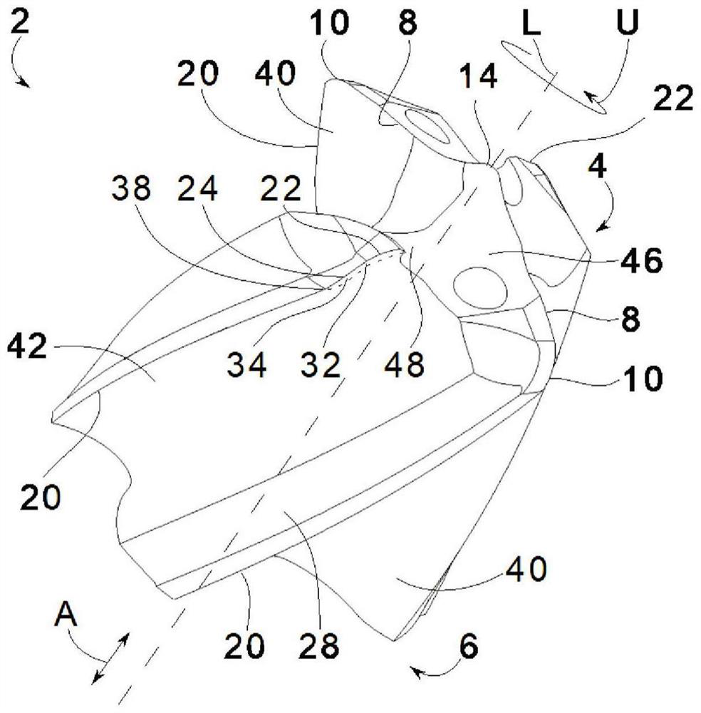
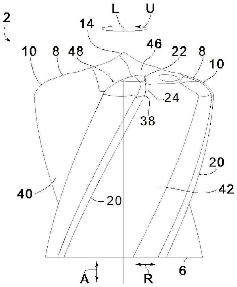
[0039] Figure 1-4 A design example of a drill 2 for machining a workpiece not depicted by drilling is shown. In general, the drill 2 is a rotary tool extending along a longitudinal axis L around which the drill 2 rotates in a direction of rotation U during operation. figure 1 A front view of the drill 2 is shown, figure 2 shows a perspective view, and image 3 and 4 shows the corresponding side view, whereby image 3 The view is from Figure 4 The view in is rotated by 90° in the direction of rotation U. The drill 2 comprises a drill point 4 formed on the front side of the drill 2 and thus facing the workpiece during operation. In the design example shown, the drill tip 4 is formed in one piece with the base body 6 of the drill 2 , ie monolithically. In an alternative not depicted, the drill tip 4 is configured as a cutting insert of the base body 6 of the drill 2 .

[0040] The drill tip 4 comprises at least one main cutting edge 8 with a cutting corner 10 extending...


PUM


Abstract

The invention relates to a drill (2) comprising a drill tip (4), wherein the drill tip (4) comprises at least one main cutting edge (8) having a cutting corner (10), from which the main cutting edge (8) extends to a center (12), wherein the drill tip (4) comprises at least one additional cutting edge (22) having an additional cutting corner (24), from which the additional cutting edge (22) extends in the direction of the center (12), wherein the additional cutting edge (22) is formed only on an outer portion (26) of the drill tip (4) and is thus shorter than the main cutting edge (8), wherein the additional cutting corner (24) projects beyond the cutting corner (10).

Description

technical field [0001] The invention relates to a drill. Background technique [0002] Drills are used to machine workpieces by drilling holes. For this purpose, the drill comprises a drill point with two main cutting edges which, for example when the drill is rotated about the longitudinal axis, strip chips away from the workpiece. As a result, the front part of the drill is sometimes subjected to heavy loads, which leads to wear. Usually radially outwards, the wear is greatest, so damage usually occurs there first. The so-called cutting corners which form the outer ends of the respective main cutting edges are especially affected. The service life of the drill is mainly limited by the wear of the cutting corners. [0003] KR 101 000 863 B1 describes a drill which, in addition to two main cutting edges, comprises two further auxiliary cutting edges formed between the main cutting edges. The auxiliary cutting edge has a length corresponding to 0.4 times the radius of th...

Claims


Application Information

Patent Timeline
Patent Type & Authority Applications(China)
IPC IPC(8): B23B51/02B23B51/06
CPCB23B51/02B23B51/06B23B2251/18B23B2251/14B23B2251/408B23B2251/204B23B2251/241
Inventor H.考珀J.施瓦格尔C.施特劳赫曼
Owner KENNAMETAL INC
Learn More