Unlock instant, AI-driven research and patent intelligence for your innovation.

Shifting device

A technology of displacement device and installation mechanism, which is applied to mobile frames, moving accessories, engine frames, etc., can solve the problems of manual moving and lack of displacement devices, and achieves small occupied space, high-efficiency lifting and shifting and The effect of adjustment

Pending Publication Date: 2021-10-19
HEFEI UNIV OF TECH
View PDF0 Cites 0 Cited by
  • Summary
  • Abstract
  • Description
  • Claims
  • Application Information

AI Technical Summary

Problems solved by technology

Especially in the current market, the height of the bed and the seat is different, and there is a lack of suitable shifting device to place the limb rehabilitation training equipment in a suitable position. In most cases, it needs to be moved manually

Method used


Image

  • Shifting device
  • Shifting device
  • Shifting device

Examples


Embodiment 1

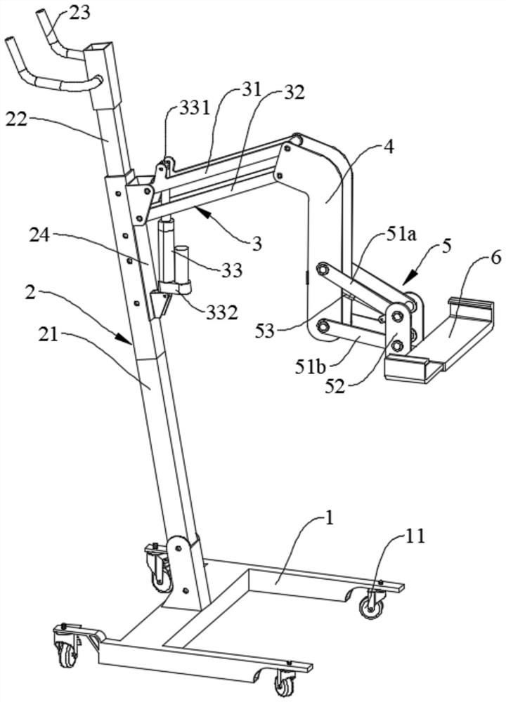
[0052] figure 1 A schematic perspective view of the three-dimensional structure of the displacement device of this embodiment is shown. see figure 1 , in this embodiment, the displacement device includes a base 1 , a support frame 2 , a displacement adjustment mechanism 3 , a first connection mechanism 4 , a second connection mechanism 5 and a mounting mechanism 6 .

[0053] see figure 1, in this embodiment, the bottom of the base 1 is equipped with a moving wheel 11, so that the entire shifting device can be easily moved, and the moving wheel 11 can be a universal wheel with a locking device, so that the shifting device can be easily moved Move to the designated position and fix it by locking device. Of course, in some embodiments, the base 1 may not be provided with the moving wheels 11, but it may be stabilized by using various methods such as quick clamps against the base 1, wherein the quick clamps are based on the dual The mechanical principle of the rocker structure...

Embodiment 2

[0070] Such as Figure 5 As shown, this embodiment introduces another displacement device, which also includes a base 1 , a support frame 2 , a displacement adjustment mechanism 3 , a first connection mechanism 4 , a second connection mechanism 5 and a mounting mechanism 6 . Compared with the displacement device in Embodiment 1, the difference is that the structure of the second connecting mechanism 5 is different, and the other structures are basically the same, so the description will not be repeated.

[0071] see Figure 5 , in this embodiment, the second connecting mechanism 5 includes a second connecting rod 51 and a second electric push rod 53; the second connecting rod 51 adopts a spoon-shaped structure, and one end of the second connecting rod 51 is connected to One end of the first connecting mechanism 4 that is not connected to the displacement adjustment mechanism 3 is rotationally connected, and the other end of the second connecting rod 51 is fixedly connected to...

Embodiment 3

[0077] Such as Figure 7 As shown, this embodiment introduces the third displacement device, which also includes a base 1 , a support frame 2 , a displacement adjustment mechanism 3 , a first connection mechanism 4 , a second connection mechanism 5 and a mounting mechanism 6 . Compared with the displacement device in Embodiment 1, the difference is that the structure of the second connecting mechanism 5 is different, and other structures are basically the same, so the description will not be repeated.

[0078] see Figure 7 , in this embodiment, the second connecting mechanism 5 is a pair of connecting rods symmetrically arranged on both sides of the first connecting mechanism 4, one end of the second connecting mechanism 5 is connected to the first connecting mechanism 4 One end of the second connecting mechanism 5 that is not connected to the displacement adjustment mechanism 3 is fixedly connected, and the other end of the second connecting mechanism 5 is fixedly connected...


PUM


Abstract

The invention discloses a shifting device. The device comprises: a base; a support frame which is fixed on the base; a displacement adjusting mechanism; a first connection mechanism; and a mounting mechanism which is arranged at one end of the first connection mechanism. The displacement adjusting mechanism comprises a first upper connecting rod, a first lower connecting rod and a first electric push rod; the first upper connecting rod is parallel to the first lower connecting rod, and the first upper connecting rod is located above the first lower connecting rod. one ends of the first upper connecting rod and the first lower connecting rod are rotationally connected with the supporting frame, and the other ends of the first upper connecting rod and the first lower connecting rod are rotationally connected with the other end of the first connection mechanism; and one end of the first electric push rod is rotationally connected with the first upper connecting rod or the first lower connecting rod, and the other end of the first electric push rod is rotationally connected with the supporting frame. According to the shifting device, high-efficiency lifting shifting and adjustment are achieved through the parallelogram structure, and the device to be shifted generates large displacement through small displacement of the push rod.

Description

technical field [0001] The invention relates to the technical field of health equipment, in particular to a displacement device. Background technique [0002] With the aging of our country's population and the increasing number of patients with unhealthy limbs, physical rehabilitation training equipment has been widely used. Different limb rehabilitation training equipment has different use postures, and a single limb rehabilitation training equipment may also have multiple use modes, so it is necessary to properly shift the limb rehabilitation training equipment or fix it in a designated position to meet the needs of different groups of people. , takes up little space when not in use. Especially in the current market, the heights of the bed and the seat are different, and there is no suitable shifting device to place the limb rehabilitation training equipment in a suitable position. In most cases, it needs to be moved manually. [0003] Therefore, it is particularly impor...

Claims


Application Information

Patent Timeline
Patent Type & Authority Applications(China)
IPC IPC(8): A63B71/00A63B23/035F16M3/00
CPCA63B71/0036A63B23/035F16M3/00A63B2210/50
Inventor 王勇汪金龙刘郑倪军穆景颂刘正士
Owner HEFEI UNIV OF TECH