Method and device for semi-automatically correcting target tracking frame, and electronic equipment

A target tracking and semi-automatic technology, applied in image enhancement, image analysis, instruments, etc., can solve the problems of reducing the tracker’s interception distance to the target, background information interference of segmentation results, easy tracking to the background, etc., to solve the problem of fast changing tracking target , Effective and accurate tracking of targets, and convenient operation process

Active Publication Date: 2021-12-14
WUHAN GUIDE INFRARED CO LTD +1
View PDF7 Cites 0 Cited by
  • Summary
  • Abstract
  • Description
  • Claims
  • Application Information

AI Technical Summary

Problems solved by technology

[0004] When the target is initially locked, due to the complex ground scene, the distance between the tracker and the target is long, and the target imaging pixels are few, rain, fog, snow, and sand and dust will seriously attenuate the energy radiated by the target, which greatly reduces the interception of the target by the tracker Distance; the ground background's reflection of sunlight and its own heat radiation make it difficult for the tracker to find the target in the background
Therefore, there may be a pixel deviation between the position of the tracking point and the position of the center point of the target when locking, and the initial deviation tends to accumulate continuously during the tracking process, and the error increases at the end of the tracking, which in turn affects the hit probability
Therefore, we need to solve problem 1: the problem of real-time detection, locking and recognition of weak and small targets with low signal-to-noise ratio in complex backgrounds
[0005] At the same time, as the distance between the tracker and the target approaches, due to the different approaching angles, the affine perspective relationship in the scene changes, and the three-dimensional relative positional relationship between the background around the target and the target is reflected in the

Method used


Image

  • Method and device for semi-automatically correcting target tracking frame, and electronic equipment
  • Method and device for semi-automatically correcting target tracking frame, and electronic equipment
  • Method and device for semi-automatically correcting target tracking frame, and electronic equipment

Examples


Embodiment Construction

[0052] The following will clearly and completely describe the technical solutions in the embodiments of the present invention with reference to the accompanying drawings in the embodiments of the present invention. Obviously, the described embodiments are only some of the embodiments of the present invention, not all of them. Based on the embodiments of the present invention, all other embodiments obtained by persons of ordinary skill in the art without making creative efforts belong to the protection scope of the present invention.

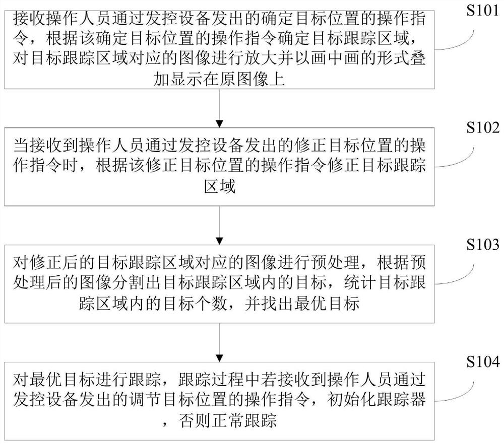
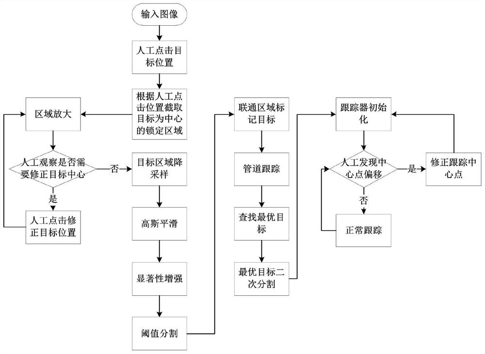
[0053] Such as figure 1 and figure 2 As shown, the embodiment of the present invention provides a method for semi-automatically correcting the target tracking frame, including the following steps:

[0054] S101. Receive the operation instruction for determining the target position issued by the operator through the launch control device, determine the target area according to the operation instruction for determining the target position, enlarg...


PUM


Abstract

The invention provides a method and a device for semi-automatically correcting a target tracking frame, and electronic equipment. The method comprises the following steps: receiving an operation instruction which is sent by an operator through launch control equipment and is used for determining a target position, amplifying an image corresponding to a target region, and displaying the amplified image on an original image in a picture-in-picture manner; when an operation instruction for correcting the target position sent by the operator through the launch control equipment is received, correcting the target region according to the operation instruction for correcting the target position; preprocessing the corrected image corresponding to the target region, segmenting targets in the target region, and finding out an optimal target; tracking the optimal target, if the operation instruction sent by an operator through the launch control equipment for adjusting the position of the target is received in a tracking process, initializing a tracker, and otherwise, performing normal tracking. According to the method and the device, the tracking precision of lock-turn tracking can be further improved, and the targets can be tracked more effectively and accurately.

Description

technical field [0001] The invention relates to the field of image tracking algorithms, in particular to a method, device and electronic equipment for semi-automatically correcting a target tracking frame. Background technique [0002] Object detection techniques are commonly used in object tracking systems. Target detection is generally divided into two stages, the first stage is the operator locks the target, and the second stage is the target tracking frame correction. One of the difficulties is to accurately detect the target, determine the position of the target tracking center and the size of the tracking frame. [0003] The image tracking system currently uses two types of input video images: TV and infrared, and the ground targets are generally vehicles, buildings and other targets. In the image tracking system, after the image is transmitted to the launch control receiver through optical fiber or wireless data link, the operator can identify the specific position ...

Claims


Application Information

Patent Timeline
IPC IPC(8): G06T3/40G06T5/00G06T7/11G06T7/136G06T7/62
CPCG06T5/002G06T7/11G06T7/136G06T3/4007G06T7/62
Inventor 黄立李颖
Owner WUHAN GUIDE INFRARED CO LTD
Why Eureka
Try Eureka