Pneumatic wrench

A technology of pneumatic wrench and airway, applied in the field of pneumatic wrench, which can solve the problems of cumbersome operation process of rotating handle, complex structure of pneumatic wrench, and limitation of rotation angle, etc., and achieve convenient and fast operation process, simple and light overall structure, and easy assembly Effect

Active Publication Date: 2021-10-22
YUEH CHI ENTERPRISE
View PDF7 Cites 0 Cited by
  • Summary
  • Abstract
  • Description
  • Claims
  • Application Information

AI Technical Summary

Problems solved by technology

However, although the handle of the above-mentioned pneumatic wrench can rotate relative to the tool head, the rotation angle is limited. For example, the handle can only rotate 45 degrees around its axis at a time, and the user cannot arbitrarily determine the rotation angle. Therefore, the processing operation will still be limited by the working environment; and when the user wants to rotate the handle, he must first loosen a positioning piece located between the tool head and the handle before further rotating the handle. After reaching the desired angle, the positioning part must be tightened again before processing can be performed. It shows that the operation process of rotating the handle is cumbersome, and the structure of the pneumatic wrench is therefore more complicated.

Method used


Image

  • Pneumatic wrench
  • Pneumatic wrench
  • Pneumatic wrench

Examples


Embodiment Construction

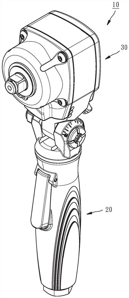
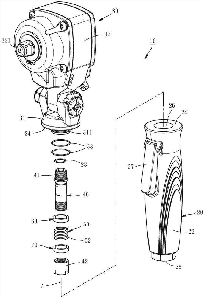
[0028] The technical contents and features of the present invention will be described in detail below through a preferred embodiment in conjunction with the accompanying drawings, as figure 1 , figure 2 Shown is an air wrench 10 provided by a preferred embodiment of the present invention, which includes a handle 20 , a tool head 30 , a pipe 40 , a compression spring 50 , an upper washer 60 , and a lower washer 70 .

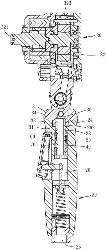
[0029] The handle 20 has a cylindrical body 22, a first annular surface 24 positioned at the upper end of the body 22, an air inlet 25 positioned at the lower end of the body 22, an air inlet 25 that passes through the body 22 and connects with the air inlet. The lower air passage 26 communicated with the mouth 25, a push button 27, and an airtight ring 28. Please refer to image 3 , Figure 4 , the lower airway 26 has a narrow opening 261, an upper chamber 262 communicating with the narrow opening 261, a lower chamber 263 communicating with the narrow opening...


PUM


Abstract

The invention provides a pneumatic wrench. The pneumatic wrench comprises a handle, a tool head, a pipe fitting and a compression spring, wherein the tool head can move between a close position and a far position relative to the handle, the handle comprises a first annular connecting face, the tool head comprises a second annular connecting face, when the tool head is located at the close position, the second annular connecting face abuts against the first annular connecting face, the compression spring exerts acting force on the pipe fitting so that the pipe fitting can drive the tool head to move towards the close position, when the tool head is located at the far position, the second annular connecting face is separated from the first annular connecting face, and at the moment, the handle can rotate by any angle relative to the tool head according to the requirement of a user, and the operation process of rotating the handle is convenient and rapid, even the pneumatic wrench can be operated by a single hand, and in addition, the pneumatic wrench is simple and light in overall structure.

Description

technical field [0001] The invention relates to a hand-held pneumatic tool, in particular to a pneumatic wrench. Background technique [0002] Because the tool head and the handle of the known pneumatic wrench are relatively fixed, users often cannot press the pneumatic wrench smoothly at an appropriate operating angle due to the narrow working environment or other obstacles. switch, causing inconvenience in processing operations. For this reason, some operators have developed a pneumatic wrench, the handle of which can be rotated relative to the tool head, so that the user can adjust the required angle according to the working environment to perform the work smoothly. However, although the handle of the above-mentioned pneumatic wrench can rotate relative to the tool head, the rotation angle is limited. For example, the handle can only rotate 45 degrees around its axis at a time, and the user cannot arbitrarily determine the rotation angle. Therefore, the processing opera...

Claims


Application Information

Patent Timeline
Patent Type & Authority Applications(China)
IPC IPC(8): B25B21/00B25B23/16
CPCB25B21/00B25B23/16
Inventor 何全政
Owner YUEH CHI ENTERPRISE
Why Eureka
Try Eureka