Body weight-activated scooter

a body weight and active technology, applied in the field of scooters, can solve the problems of affecting the efficiency of the vehicle, undue stress, and loss of power in the drive-train system, so as to prolong the coasting motion, increase the speed of the ride, and increase the rid

Inactive Publication Date: 2007-05-24
TAL YAIR
View PDF11 Cites 44 Cited by
  • Summary
  • Abstract
  • Description
  • Claims
  • Application Information

AI Technical Summary

Benefits of technology

[0013] The scooter of the present invention, in a preferred embodiment thereof, bears most of the weight of a rider on the rear, vertical chassis section which is aligned with a vertical gravity line and therefore frees the rest of the structural parts of the scooter, such as the front axle, from any weight-bearing load. This construction and weight distribution shifts the major part of the weight of a person to the heelward portion of each of a pair of treadles which is substantially disposed at the rear, vertical section. On such a chassis there is almost only the pushing pressure from operation of the scooter and this allows it to be very light-weight in construction.
[0015] The pair of treadles are each connected at their heelward ends to one end of each corresponding V-belt via stirrup-like springs supporting the heelward ends and introduced to reduce vibration. The other end of each of the V-belts is connected to each of a corresponding pair of longer, return springs which operate to reverse the direction of pull of the pair of V-belts and to maintain tension.
[0016] The pair of systems of the present invention works by a rider alternately lifting and depressing his feet on the pair of treadles, as desired. The operation is effected by direct placement of the heels of a rider, in a stepping action, at the extreme rear point on the pair of treadles in line with the gravity vector so as to maximize the weight vector on the pair of V-belts and to create forward thrust which is transferred to at least one rear drive wheel.
[0022] an over-running clutch drive mounted on the rear axle and mechanically connected to the at least one rear drive-wheel and linked to the weight-vector wheel via the looped linking means, the overrunning clutch drive providing sustained forward thrust when the treadle is depressed by the weight of a rider on the heelward end and the scooter is operated.
[0023] The scooter of the present invention, in a preferred embodiment thereof, is operated by the weight of the body through small, controlled, foot movements, which, when applied to one of the pair of treadles, moves the scooter forward with sustained forward thrust. In effect, the scooter exploits the weight of the body while “stepping” in place to generate a forward motion. When a user pauses between “steps”, the scooter coasts freely. To lengthen coasting motion, the user simply resumes the “stepping” action and it is not necessary to use a push with a free foot against the ground or surface to regain momentum as is done with a children's scooter. The scooter is especially suited for use on flat, paved areas, such as city streets, sidewalks, broad plazas, and shopping and recreational centers since it is not motorized.
[0026] The scooter is intended for smooth, flat surfaces which will help people who have walking difficulties; only a small lifting of the heel of the foot is sufficient to create a driving “pulse”. The device of the invention is relatively inexpensive and does not require a motor. It is therefore also quiet in operation and pollution-free to the environment.

Problems solved by technology

Sandgren employs a lateral, cross-over arrangement for the linking means which impacts negatively on the efficiency of the vehicle as described and causes loss of power in the drive-train system.
This construction is problematic due to the possibility of uneven and perhaps undue stress on the connections of the lever from the foot pressure of the rider on the treadle.
In Bailey there is described a three-wheeled vehicle which also utilizes a lateral, cross-over linking system with its inherent power loss and inefficiency.
These construction features add to the cost of manufacture and make the vehicle more expense for youth and senior citizens to purchase.

Method used


Image

  • Body weight-activated scooter
  • Body weight-activated scooter
  • Body weight-activated scooter

Examples


Embodiment Construction

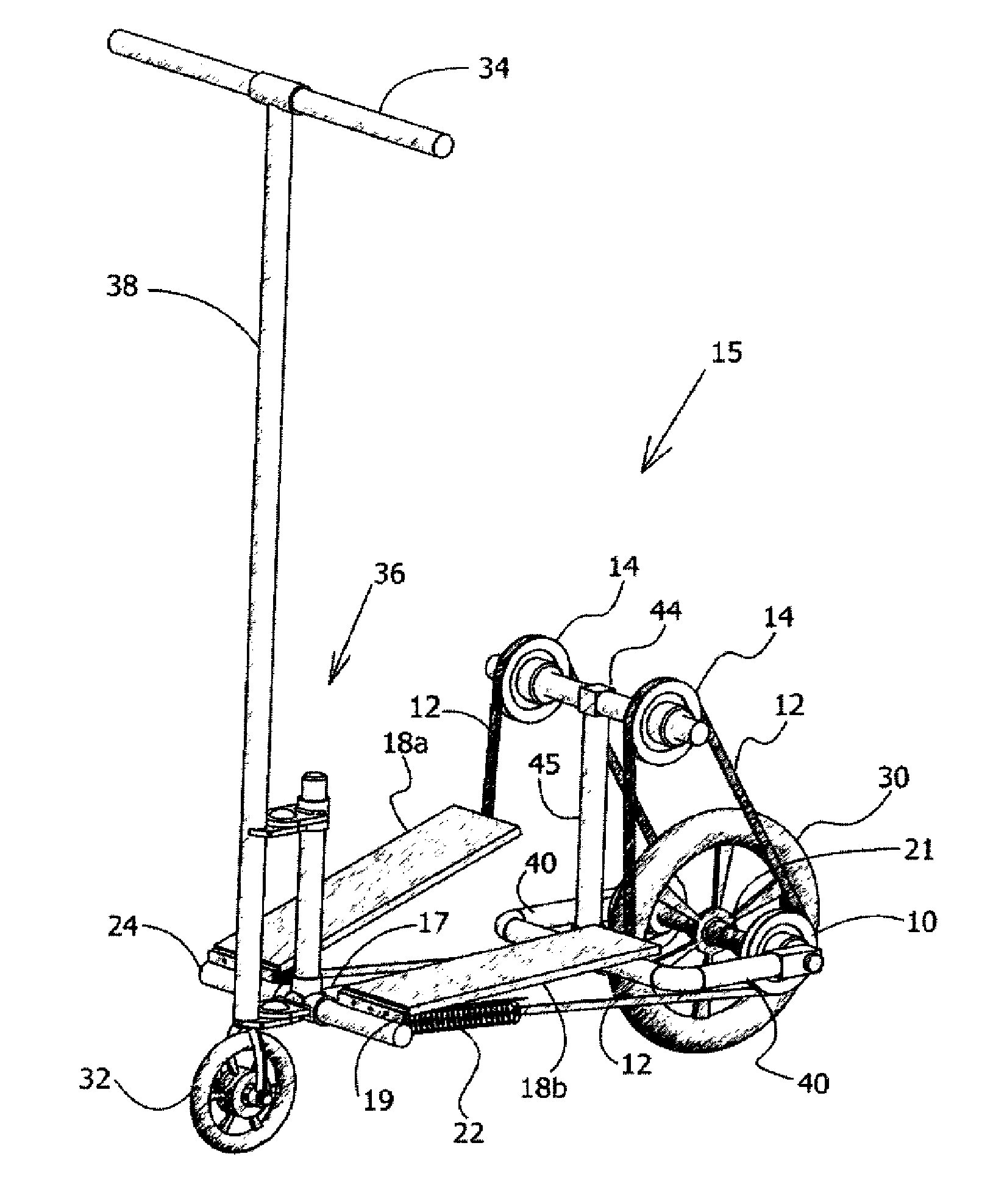
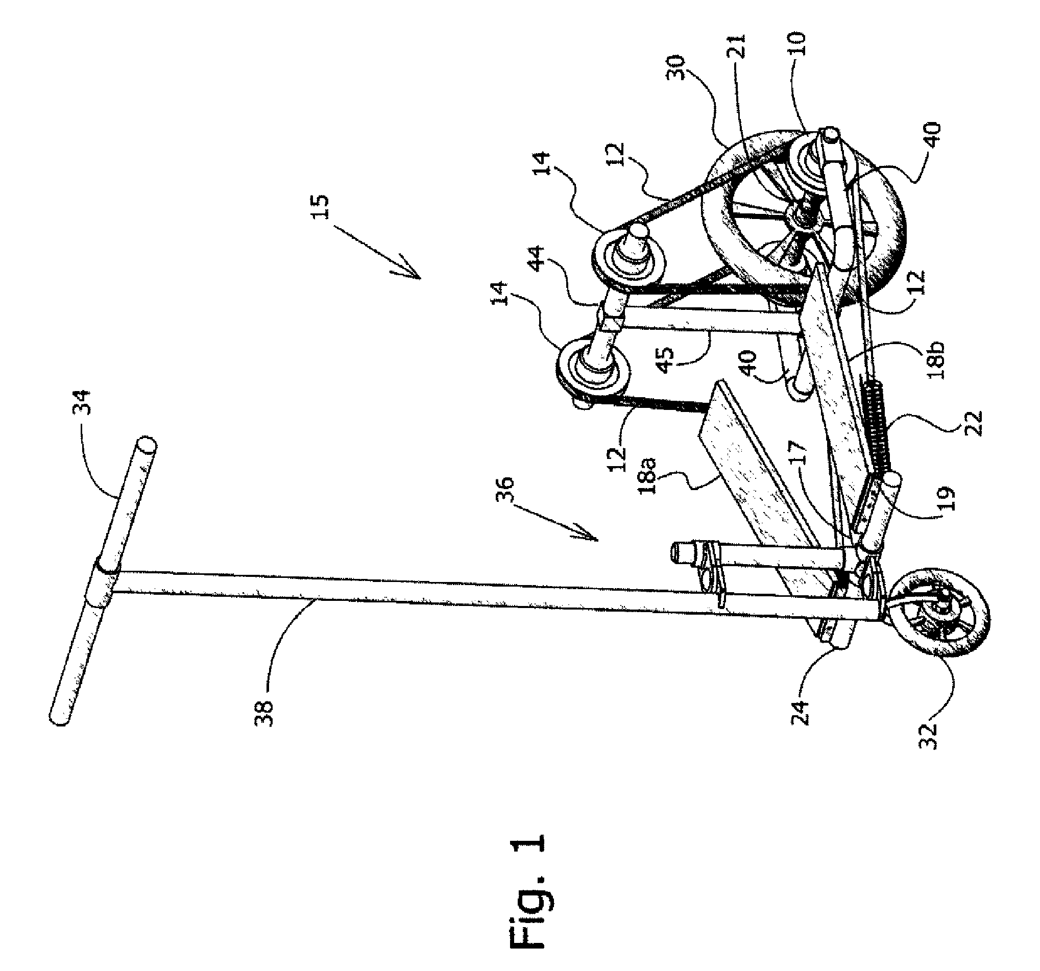
[0034]FIG. 1 is a general isometric view of a two-wheeled scooter constructed in accordance with a preferred embodiment of the invention.

[0035] A two-wheeled scooter 15 comprises steering handlebars 34 mounted on an extendible upright, steering rod 38 rotatably connected to a steering mechanism 36 mechanically attached to the front portion of scooter 15. The height of handlebars 34 is set to accommodate the average height of a rider, but, optionally, may be constructed so as to be adjustable (not shown). A light-weight chassis 17 supports a pair of individually operated treadles 18a and 18b. Steering rod 38 controls the turning of front steering wheel 32. Although only one front steering wheel is shown, by way of example, it is obvious to those skilled in the art that more than one can be used to provide greater stability or improved turning characteristics.

[0036] Treadles 18a / b are pivotably attached at their respective front ends to hinges 19 mounted on lateral extensions 24 of ...


PUM


Abstract

A body weight-activated scooter having a rear, vertical chassis section and at least one front steering wheel mounted on a front chassis section and at least one rear drive-wheel, the scooter provided with a pair of systems substantially in alignment with a vertical gravity line for transferring power to at least one rear drive-wheel, each of the pair of systems comprising: a treadle bearing most of the weight of a rider at a heelward end; a weight-vector wheel; a return tension means; and an over-running clutch drive connected to the at least one rear drive-wheel and linked to the weight-vector wheel via a linking means, the over-running clutch drive providing sustained forward thrust when the treadle is depressed by the weight of a rider on the heelward end and the scooter is operated.

Description

CROSS-REFERENCE TO RELATED APPLICATION [0001] The present application is a Continuation-in-Part of U.S. patent application Ser. No. 11 / 108,075 filed Apr. 18, 2005 by the Applicant.FIELD OF THE INVENTION [0002] The present invention relates generally to scooters, and more particularly to a body weight-activated scooter utilizing over-running clutch drives in conjunction with weight-vector wheels for generating forward motion. BACKGROUND OF THE INVENTION [0003] The world population, especially in Western societies, resides more and more in flat, smooth places, either naturally so, or made so by urban construction (due to paving). Localities and areas that are not smooth and flat can be improved and developed into areas more suitable to the use of “wheeled feet” thus easing the task of using one's feet rather than expending time, energy, and money on using motorized transport. In many cases, urban centers are being closed to all but foot traffic to limit the “grid-lock” of vehicular co...

Claims


Application Information

Patent Timeline
Patent Type & Authority Applications(United States)
IPC IPC(8): B62M1/00B62M1/24
CPCB62K3/002B62M1/28
Inventor TAL, YAIR
Owner TAL YAIR
Why Eureka
Try Eureka