Heat exchanger

A technology of heat exchangers and connectors, which is applied in the direction of fixing heat exchangers, heat exchange equipment, heat exchanger shells, etc., and can solve problems such as increased operating procedures

Pending Publication Date: 2022-01-11
DENSO CORP
View PDF6 Cites 0 Cited by
  • Summary
  • Abstract
  • Description
  • Claims
  • Application Information

AI Technical Summary

Problems solved by technology

[0009] In Patent Document 1, since the reinforcement plate is used for the reinforcement of the header tank, parts other than necessary are required, and the work process increases

Method used


Image

  • Heat exchanger
  • Heat exchanger
  • Heat exchanger

Examples


Embodiment Construction

[0021] Hereinafter, this embodiment will be described with reference to the drawings. In order to facilitate understanding of the description, in each drawing, the same reference numerals are assigned to the same constituent elements as much as possible, and overlapping descriptions are omitted.

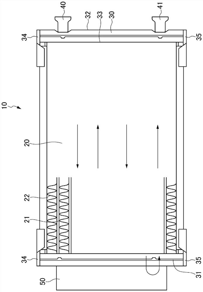
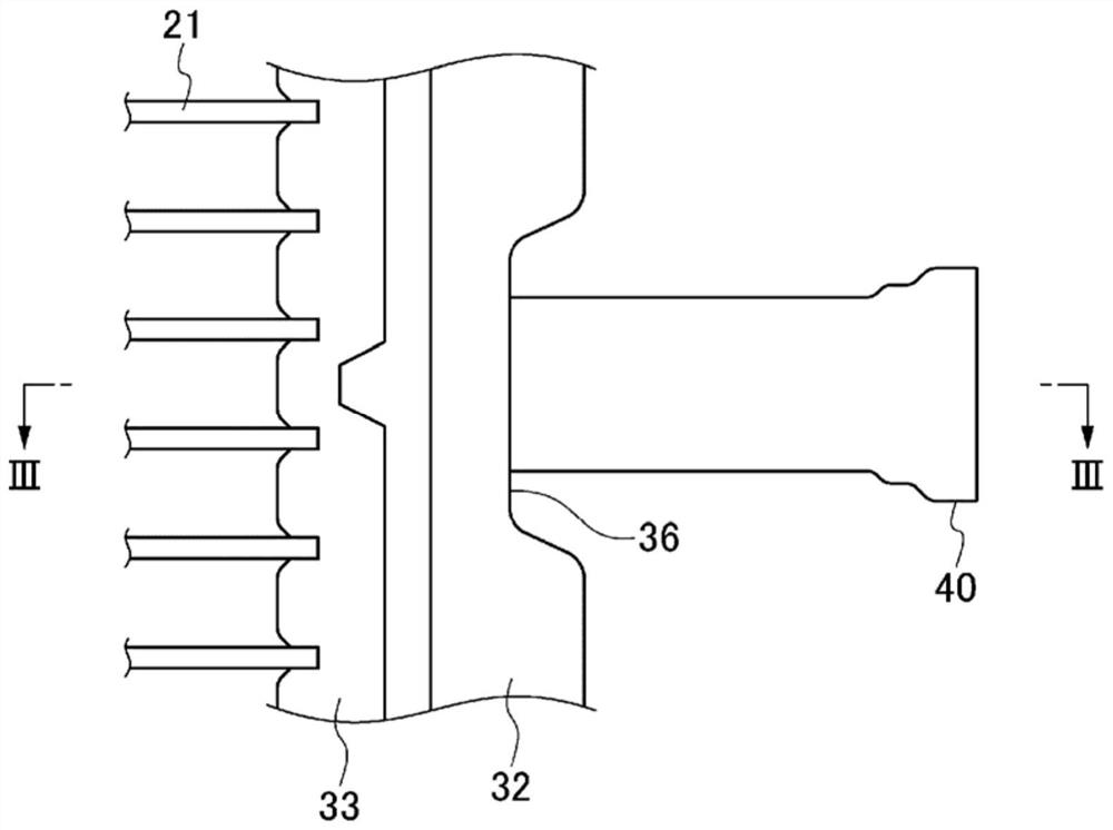
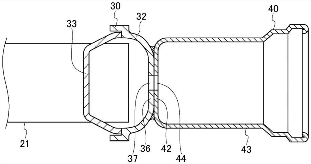
[0022] refer to figure 1 , and a heat exchanger according to one embodiment will be described. The heat exchanger 10 is used, for example, as a condenser of an air conditioner mounted on a mobile body such as a vehicle. Such as figure 1 As shown, the heat exchanger 10 includes, for example, a core 20 , a pair of tanks 30 and 31 , connectors 40 and 41 , and a conditioning tank 50 . Each member is made of, for example, aluminum or an aluminum alloy, and is fixed by brazing after being temporarily fixed by fitting, riveting, clamping, or the like.

[0023] The core 20 includes a plurality of tubes 21 and a plurality of fins 22 . Refrigerant flows inside the plurality of tubes 21 . ...


PUM


Abstract

This heat exchanger comprises: a pair of tanks that are provided at both ends of a plurality of stacked tubes (21) and have a longitudinal direction along the direction in which the tubes are stacked; and a connector (40) on the side surface of a connection tank (30), which is at least one of the pair of tanks, the connector being for connecting a pipe to the connection tank. The connection tank has a tubular shape having a flat portion (36) on at least a portion of the side surface. The connector is joined to the flat portion such that at least a portion of the facing surface (42) facing the flat portion projects from the flat portion in the lateral direction of the connection tank.

Description

[0001] Cross-reference of related applications [0002] This application is based on Japanese Patent Application No. 2019-100338 filed on May 29, 2019, the benefit of priority is claimed, and the entire contents of this patent application are incorporated herein by reference. technical field [0003] The present invention relates to a heat exchanger. Background technique [0004] Conventionally, in heat exchangers mounted on automobiles, etc., there is known a structure in which a portion of a side surface of a curved header box is cut when joining a connector for connecting the header box and piping to the header box. Machining forms the flat portion, and the connector is engaged with the flat portion. When high-temperature and high-pressure refrigerant is supplied to such a heat exchanger, since the flat portion of the header tank is deformed from the inside toward the outside by applying pressure to the header tank from the inside, stress may concentrate on the header ta...

Claims


Application Information

Patent Timeline
Patent Type & Authority Applications(China)
IPC IPC(8): F25B39/04F28F9/18F28F9/26F28F9/22
CPCF25B39/04F28F9/18F28F9/26F28F9/22F28D1/05375F28F9/001F28D2021/0091F28D2021/0084F28F21/084F28F2275/04F28F9/0224F28F9/0248F28F2225/08F16L41/082B23K2101/14B23K2103/10B23K3/087F28D7/16F28F9/02
Inventor 饭尾正信泷濑真一郎
Owner DENSO CORP
Why Eureka
Try Eureka