Piezoelectric power generator

A piezoelectric power generation and piezoelectric body technology, applied in the manufacture/assembly of piezoelectric/electrostrictive devices, generators/motors, piezoelectric/electrostrictive/magnetostrictive devices, etc., can solve large loads, Problems such as deformation of piezoelectric elements and difficulty in power generation efficiency, etc., to achieve the effect of high power generation efficiency

Active Publication Date: 2017-12-01
MURATA MFG CO LTD
View PDF8 Cites 0 Cited by
  • Summary
  • Abstract
  • Description
  • Claims
  • Application Information

AI Technical Summary

Problems solved by technology

Therefore, in order to deform the piezoelectric element, a large load is required, and it is difficult to improve power generation efficiency.

Method used


Image

  • Piezoelectric power generator
  • Piezoelectric power generator
  • Piezoelectric power generator

Examples


no. 1 approach

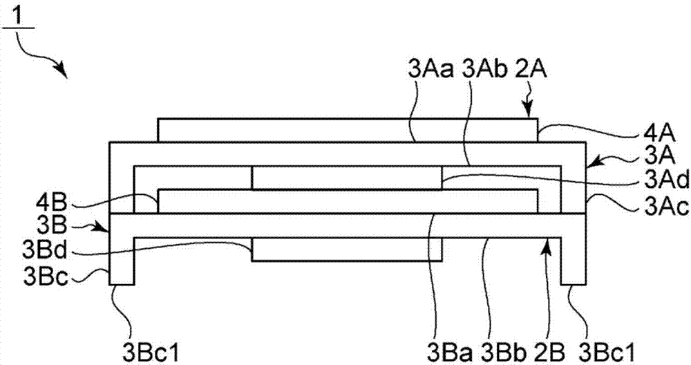
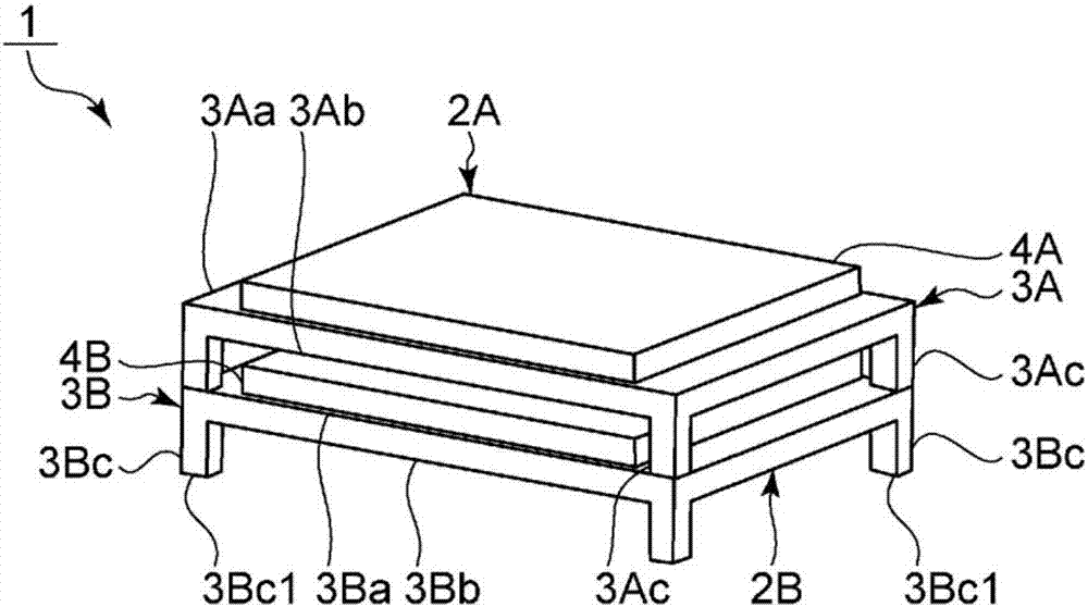
[0051] figure 1 It is a front view of the piezoelectric generator according to the first embodiment of the present invention. figure 2 It is a perspective view of the piezoelectric generator of the first embodiment.

[0052] Such as figure 1 As shown, the piezoelectric power generating device 1 has a first power generating element 2A and a second power generating element 2B. exist figure 1 Among them, the first power generating element 2A is provided on the second power generating element 2B.

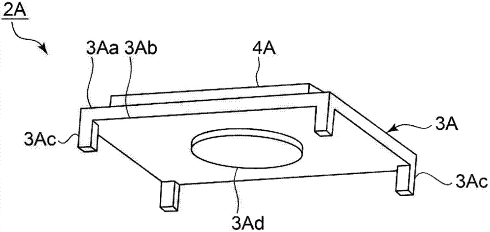
[0053] The first power generating element 2A has a support body 3A and a piezoelectric body 4A.

[0054] The support body 3A is made of, for example, a conductive material such as a metal or an alloy, or an insulating material such as a ceramic material. The support body 3A has a flat part, a convex part 3Ad, and a support part 3Ac which is a leg part. The flat portion of the support body 3A, the convex portion 3Ad, and the support portion 3Ac are integrally formed. The planar p...

no. 2 approach

[0083] Figure 10 It is a front view of the piezoelectric generator of the second embodiment.

[0084] In the piezoelectric power generating device 11 , the shape of the protrusions 13Ad, 13Bd of the supports 13A, 13B of the first and second power generating elements 12A, 12B is different from that of the first embodiment. Except for the above points, the piezoelectric power generator 11 has the same configuration as the piezoelectric power generator 1 of the first embodiment.

[0085] The convex portion 13Ad of the support body 13A of the first power generating element 12A has a base portion 13Ad0 and a step portion 13Ad1 of one stage.

[0086] The base portion 13Ad0 is provided on the lower surface of the planar portion of the support body 13A. The base portion 13Ad0 protrudes from the central portion of the planar portion of the support body 13A. Base portion 13Ad0 has a circular shape when viewing support body 13A in a direction perpendicular to the lower surface of sup...

no. 3 approach

[0094] Figure 14 It is a front view of the piezoelectric generator of the third embodiment.

[0095] The piezoelectric power generating device 21 differs from the first embodiment in that it has three or more power generating elements 22 . Each power generating element 22 has the same configuration as that of the first power generating element 2A in the first embodiment.

[0096] In the piezoelectric power generating device 21, a plurality of power generating elements 22 are stacked vertically. Each power generating element 22 is overlapped similarly to the first and second power generating elements 2A, 2B of the first embodiment. When the piezoelectric body 4A of the uppermost power generating element 22 in the piezoelectric power generating device 21 is pressed downward, the piezoelectric body 4A of each power generating element 22 other than the uppermost power generating element 22 is also pressed by the support body 3A. The convex part 3Ad presses.

[0097] Here, the...


PUM


Abstract

Provided is a piezoelectric power generator that has high power generation efficiency and minimal likelihood of damaging piezoelectric bodies. The piezoelectric power generator 21 is provided with a plurality of power generation elements 22, each of which having: a support body 3A provided with a plate-shaped flat-surface part that has a main surface 3Aa and another main surface 3Ab, and a projecting part 3Ad that protrudes from the central part of the other main surface 3Ab; and a piezoelectric body 4A provided on the main surface 3Aa. The piezoelectric body 4A is disposed so as to overlap the projecting part when the support body 3A is viewed in plan view along the direction perpendicular to the main surface 3Aa. The plurality of power generation elements 22 overlap in the direction perpendicular to the main surfaces 3Aa. The support body 3A of at least one of a pair of adjacent power generation elements 22 is provided with a plurality of support parts 3Ac (legs) that protrude from a peripheral edge part further outward from the central part of the flat surface part. The plurality of power generation elements overlap, interposed by the legs 3Ac, so that the main surface 3Aa and the another main surface 3Ab of the mutual support bodies 3A face each other in the pair of adjacent power generating elements 22.

Description

technical field [0001] The present invention relates to piezoelectric generators. Background technique [0002] A piezoelectric power generator is used as a power generator using a piezoelectric element. Patent Document 1 below discloses an example of a piezoelectric generator. This piezoelectric generator has a plurality of stacked elastic bodies. Each elastic body has a disk-like shape. Each elastic body has a concave portion between the ring-shaped outer peripheral portion and the central portion. A piezoelectric element is provided in the concave portion of each elastic body. The ring-shaped outer peripheral portions of the elastic bodies contact each other and are stacked. [0003] A piezoelectric generator described in Patent Document 2 below has a pressurizing member in which a convex lens-shaped pressurizing device is provided at the center. Pressurizing members are disposed between the stacked piezoelectric elements. Each piezoelectric element is in contact w...

Claims


Application Information

Patent Timeline
Patent Type & Authority Applications(China)
IPC IPC(8): H02N2/18H01L41/053H01L41/113
CPCH02N2/18H10N30/875H10N30/30H10N30/50H10N30/88H10N30/308H10N30/872H10N30/05H10N30/063H10N30/8554
Inventor 高桥讲平上林嗣治
Owner MURATA MFG CO LTD
Why Eureka
Try Eureka