Fuel cell system

a fuel cell and system technology, applied in the field of fuel cell systems, can solve the problems of inability to inhibit the performance of the fuel cell stack from being degraded, and achieve the effect of inhibiting durability and increasing gas leakage detection accuracy

Active Publication Date: 2010-03-04
TOYOTA JIDOSHA KK
View PDF12 Cites 53 Cited by
  • Summary
  • Abstract
  • Description
  • Claims
  • Application Information

AI Technical Summary

Benefits of technology

[0017]While the possible gas leakage is being detected, the output voltage from the fuel cell is permitted to increase up to the open end voltage. Thus, the reaction gas is inhibited from being consumed by the power generation by the fuel cell during the detection of the possible gas leakage. This enables an increase in gas leakage detection accuracy.
[0018]Here, the fuel cell is a cell stack comprising a plurality of stacked cells. The control device preferably corrects the high-potential avoidance voltage so that highest one of output voltages from the plurality of cells is equal to or lower than a predetermined value. A variation in cell voltage may make the highest one of output voltages from the plurality of cells higher than the high-potential avoidance voltage per cell. The high-potential avoidance voltage is thus controlled so that highest one of output voltages from the plurality of cells is equal to or lower than the predetermined value (for example, a voltage value obtained by dividing a target voltage for the cell stack by the total number of cells). Consequently, durability can be inhibited from being degraded by the variation in cell voltage.

Problems solved by technology

Consequently, performance of the fuel cell stack needs to be inhibited from being degraded.

Method used


Image

  • Fuel cell system
  • Fuel cell system
  • Fuel cell system

Examples


Embodiment Construction

[0029]An embodiment according to the present invention will be described with reference to the drawings.

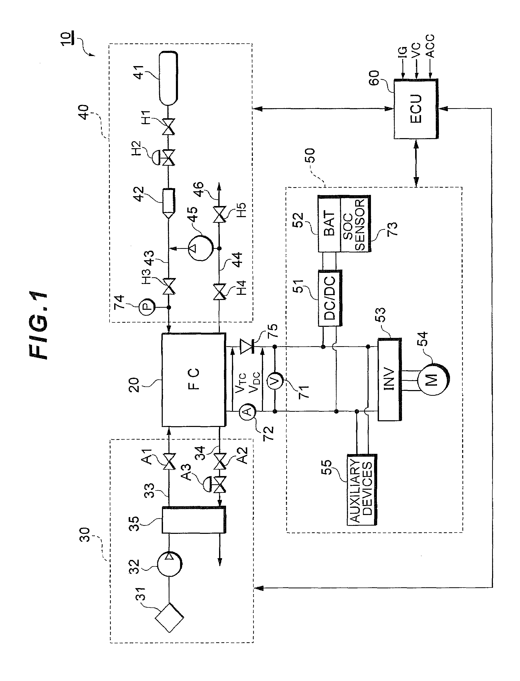
[0030]FIG. 1 shows a configuration of a fuel cell system 10 functioning as a vehicle-mounted power supply system mounted in a fuel cell vehicle.

[0031]The fuel cell system 10 functions as a vehicle-mounted power supply system mounted in the fuel cell vehicle. The fuel cell system 10 includes a fuel cell stack 20 that receives a supplied reaction gas (fuel gas and oxidation gas) to generate power, an oxidation gas supply line 30 through which air as an oxidation gas is supplied to the fuel cell stack 20, a fuel gas supply line 40 through which a hydrogen gas as a fuel gas is supplied to the fuel cell stack 20, a power line 50 that controls charging and discharging of power, and a controller 60 that integrally controls the whole system.

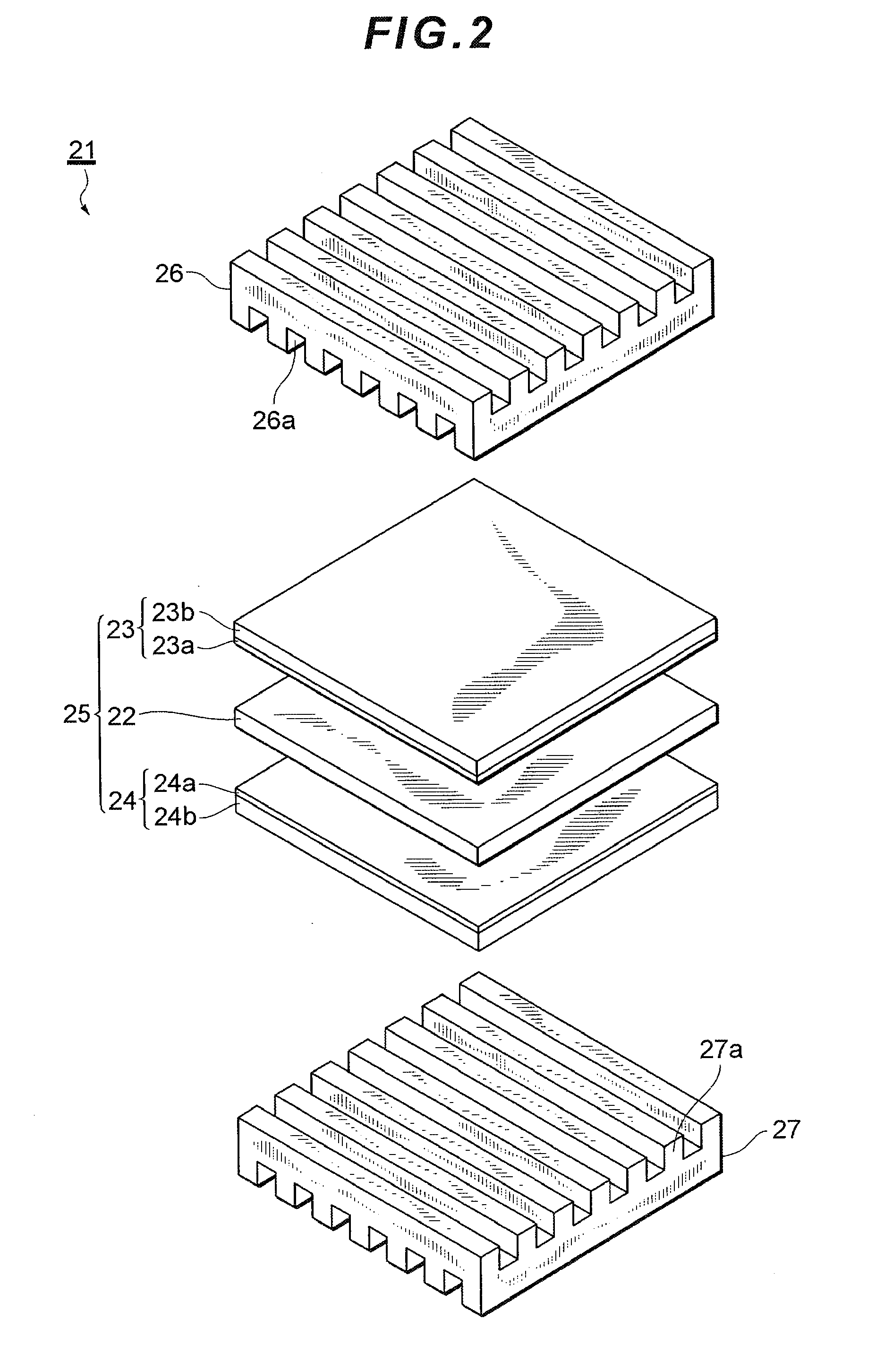
[0032]The fuel cell stack 20 is a solid polyelectrolyte cell stack made up of a large number of cells stacked in series. In the fuel cell stack 20, an...


PUM

PropertyMeasurementUnit
output voltageaaaaaaaaaa
voltageaaaaaaaaaa
pressureaaaaaaaaaa

Abstract

To provide a fuel cell system that can both improve power generation efficiency of a fuel cell and maintain durability of the fuel cell. A fuel cell system performs control such that when a power requirement for the fuel cell is lower than a predetermined value, a supply of a reaction gas to a fuel cell is stopped to keep an output voltage from the fuel cell equal to a high-potential avoidance voltage that is lower than an open end voltage. The fuel cell system further controls the output voltage from the fuel cell with the high-potential avoidance voltage set to be an upper limit when the power requirement for the fuel cell is equal to or higher than a predetermined value. By setting the upper limit of the output voltage of the fuel cell to be the high-potential avoidance voltage, which is lower than the open end voltage, the catalyst can be inhibited from being degraded by an increase in the output voltage from the fuel cell up to the open end voltage.

Description

TECHNICAL FIELD[0001]The present invention relates to a fuel cell system that controls operation of a fuel cell by setting a high-potential avoidance voltage lower than an open end voltage to be an upper limit for an output voltage from the fuel cell.BACKGROUND ART[0002]A fuel cell stack is a power generation system which oxidizes a fuel by means of an electrochemical process to emit energy as a result of an oxidation reaction and which converts the resulting energy directly into electric energy. The fuel cell stack includes a membrane-electrode assembly including a polyelectrolyte membrane through which hydrogen ions are selectively transported and paired electrodes made up of a porous material and sandwichingly holding opposite side surfaces of the polyelectrolyte membrane. Each of the paired electrodes is mainly composed of carbon power carrying a platinum-containing metal catalyst and includes a catalyst layer that is in contact with the polyelectrolyte membrane and a gas diffus...

Claims


Application Information

Patent Timeline
Patent Type & Authority Applications(United States)
IPC IPC(8): H01M8/04H01M8/00
CPCH01M8/04619H01M8/04753H01M8/04567Y02E60/50H01M8/04858H01M8/0488H01M8/04
Inventor UMAYAHARA, KENJIYOSHIDA, MICHIOMATSUMOTO, TADAICHITANIYAMA, MOTOHIKO
Owner TOYOTA JIDOSHA KK
Why Eureka
Try Eureka