
Anode and battery

Inactive Publication Date: 2005-04-14
SONY CORP
View PDF4 Cites 39 Cited by
  • Summary
  • Abstract
  • Description
  • Claims
  • Application Information

AI Technical Summary

Benefits of technology

[0018] According to the anode of the invention, lithium of 0.5% to 40% of the anode capacity is inserted. Therefore, for example, when the anode is applied to the battery of the invention, consumption of lithium due to reaction with an electrolytic solution or the like at the early cycles can be inhibited. Even when lithium is consumed, lithium can be refilled, and early deterioration can be inhibited. Further, potential raise of the anode can be inhibited in the final stage of discharge, and deterioration with the potential raise of the anode can be inhibited. Further, by previously inserting lithium, stress on the anode current collector due to expansion and shrinkage of the anode active material layer with charge and discharge can be reduced. Therefore, battery characteristics such as cycle characteristics can be improved.
[0019] In particular, when an insertion amount of lithium is in the range from 0.02 μm to 20 μm per unit area by converting to a thickness of metallic lithium, higher effects can be obtained, and handling characteristics and manufacturing characteristics can be improved.
[0020] Further, when lithium is inserted by depositing metallic lithium by vapor-phase deposition method, lithium can be inserted in the process of depositing metallic lithium, and handling becomes easy. Further, an amount of lithium to be inserted can be easily controlled, and lithium can be inserted uniformly over a large area. Further, when the anode active material layer is deposited by vapor-phase deposition method, deposition of the anode active material layer and lithium insertion process can be continuously performed, and therefore, manufacturing processes can become simplified.
[0021] Further, when the anode active material layer contains at least one from the group consisting of simple substances, alloys, and compounds of silicon or germanium, a high capacity can be obtained, and capacity loss due to previous insertion of lithium can be reduced. Further, by inserting lithium, dangling bond or impurities such as hydrogen and oxygen, which exist in the anode active material layer can be reduced, and battery characteristics such as cycle characteristics can be improved.
[0022] According to other batteries of the invention, electrochemically active lithium remains in the anode after discharge. Therefore, even when lithium is consumed due to reaction with the electrolytic solution or the like, lithium can be refilled and deterioration can be inhibited. Further, potential raise of the anode in the final stage of discharge can be further inhibited, and deterioration with the potential raise of the anode can be inhibited. In the result, battery characteristics such as cycle characteristics can be improved.

Problems solved by technology

However, in the case of using cobalt acid lithium for a cathode and graphite for an anode, which is currently a typical type for the lithium secondary batteries, the battery capacity is in a saturated state, and it is extremely difficult to greatly obtain a high capacity of the battery.
However, when charge and discharge are repeated, these high capacity anodes are pulverized and miniaturized due to significant expansion and shrinkage of an anode active material, current collecting characteristics are lowered, and dissolution reaction of an electrolytic solution is promoted due to an increased surface area, so that their cycle characteristics are extremely poor.
However, even when using this anode, the cycle characteristics are not sufficient due to a nonreversible reaction of the active material with charge and discharge.
The reaction with the electrolyte with charge and discharge causes significant deterioration of the capacity particularly at early cycles.
Further, in these high capacity anodes, as lithium is extracted, anode potential is significantly raised particularly in the final stage of discharge, which is one of the causes of deterioration of characteristics.
Therefore, previous insertion of lithium leads to significant lowering of the anode capacity, that is, there is little benefit in view of actual energy density.
Therefore, these injected lithium ions cannot play a role as a reservoir to compensate cycle deterioration, and the effect thereof is small.
Further, as diagrammatically shown in the Japanese Unexamined Patent Application Publication No. 2002-93411, when the ion injection apparatus which performs a small amount of doping by using plasma is used, an apparatus composition becomes complicated, and it is difficult to simply inject a certain amount of lithium with which effect can be obtained.
The technique thereof is not intended to improve characteristics by previously inserting lithium excessive compared to a lithium amount involved in battery reaction into the anode.

Method used


Image

  • Anode and battery
  • Anode and battery
  • Anode and battery

Examples


examples

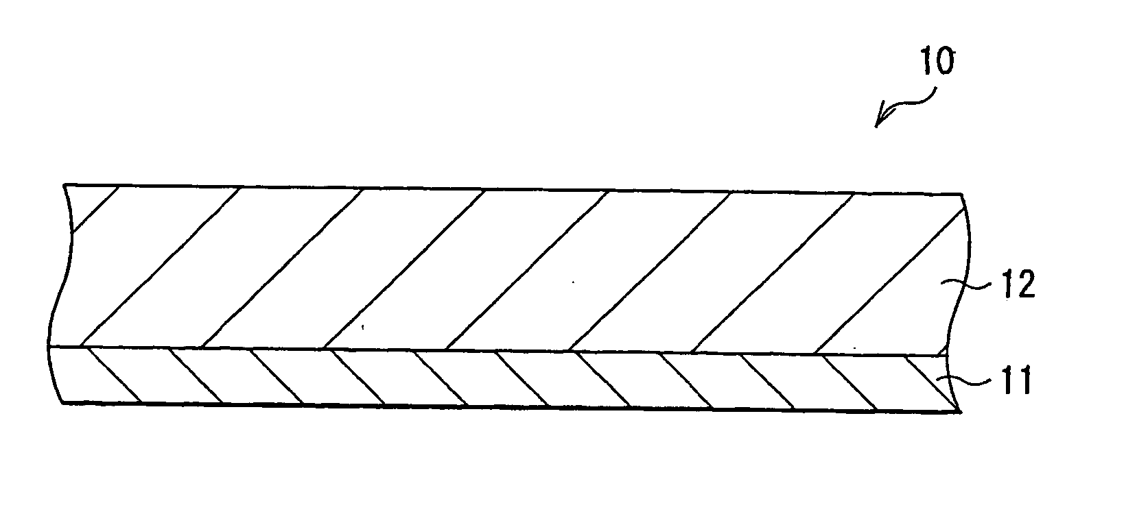
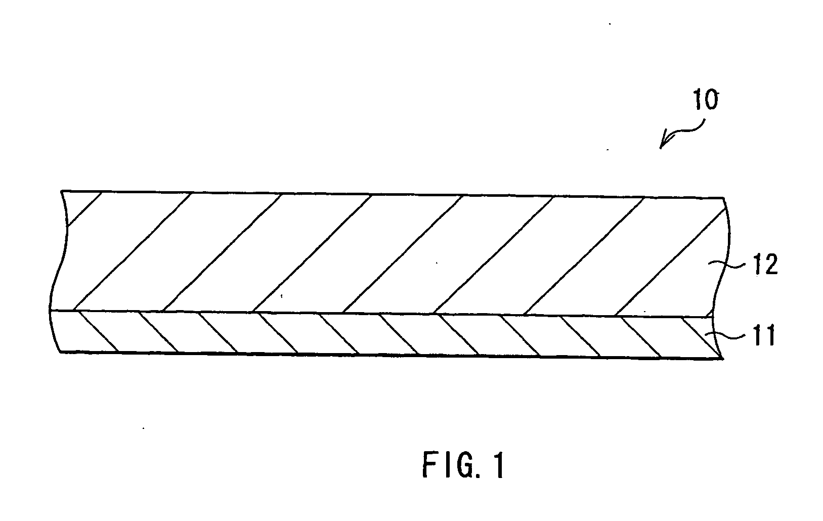
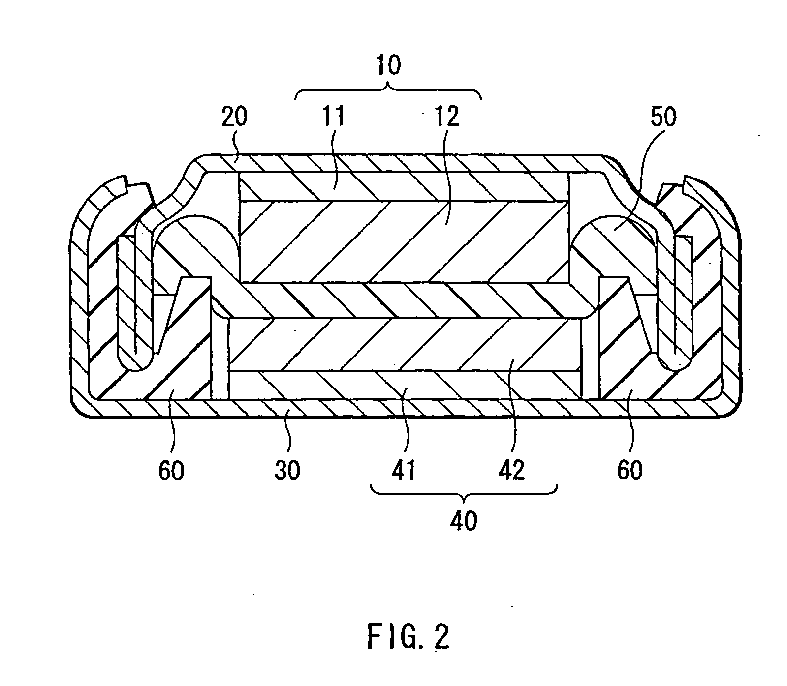
[0081] Further, concrete descriptions will be given of examples of the invention with reference to FIGS. 1 to 4. In the following examples, reference numbers and symbols used in the foregoing embodiment are correspondingly used.

examples 1-1 to 1-7

[0082] Coin type secondary batteries as shown in FIG. 2 were fabricated. First, the anode active material layer 12 made of silicon was formed on the anode current collector 11 made of a copper foil having a thickness of 15 μm by sputtering. Next, metallic lithium was deposited on the anode active material layer 12 by vacuum deposition method. An atmosphere in depositing metallic lithium was under 1×10⁻³ Pa and a deposition rate was larger than 5 nm / s. An amount of metallic lithium to be deposited, that is, an amount of lithium to be previously inserted in the anode active material layer 12 was sequentially changed as 0.5% , 1%, 5% , 10%, 20%, 30%, and 40% of a lithium insertion capacity the anode active material layer 12 had, correspondingly to Examples 1-1 to 1-7. A thickness of the anode active material layer 12 was set so that a resultant capacity from subtracting a lithium capacity previously inserted from a capacity the anode active material layer 12 had could be constant. That...

examples 2-1 to 2-7

[0094] The anodes 10 of Examples 2-1 to 2-7 and secondary batteries thereof were fabricated as in Examples 1-1 to 1-7, except that the anode active material layer 12 was formed with germanium by sputtering. As Comparative examples 2-1 to 2-3 in relation to Examples 2-1 to 2-7, anodes and secondary batteries thereof were fabricated as in Examples 2-1 to 2-7, except that an amount of lithium to be previously inserted in the anode was changed as shown in Table 2. However, regarding Comparative example 2-3, as in Comparative example 1-3, the anode was deformed too much due to insertion of lithium, and a battery could not be fabricated. Regarding the fabricated secondary batteries of Examples 2-1 to 2-7 and Comparative examples 2-1 and 2-2, the charge and discharge test was conducted as in Examples 1-1 to 1-7, and capacity retention ratios at the 50th cycle were obtained. Further, as in Examples 1-1 to 1-7, after discharge at the first cycle was finished, the anode 10 was taken out to fa...


PUM


Abstract

The invention provides an anode capable of improving battery characteristics such as cycle characteristics and a battery using it. An anode current collector is provided with an anode active material layer. The anode active material layer contains at least one from the group consisting of simple substances, alloys, and compounds of silicon or the like capable of forming an alloy with Li. Further, the anode active material layer is formed by vapor-phase deposition method or the like, and is alloyed with the anode current collector. Further, Li of from 0.5% to 40% of an anode capacity is previously inserted in the anode active material layer. Therefore, when Li is consumed due to reaction with an electrolyte or the like, Li can be refilled, and potential raise of the anode can be inhibited in the final stage of discharge.

Description

BACKGROUND OF THE INVENTION [0001] 1. Field of the Invention [0002] The present invention relates to an anode having an anode current collector and an anode active material layer, and a battery using it. [0003] 2. Description of the Related Art [0004] In recent years, in connection with high-performance and multi-function of mobile devices, high capacities of secondary batteries, the power source for the mobile devices have been desired earnestly. As a secondary battery which meets this demand, there is a lithium secondary battery. However, in the case of using cobalt acid lithium for a cathode and graphite for an anode, which is currently a typical type for the lithium secondary batteries, the battery capacity is in a saturated state, and it is extremely difficult to greatly obtain a high capacity of the battery. Therefore, from old times, using metallic lithium (Li) for an anode has been considered. However, in order to put this anode to practical use, it is necessary to improve e...

Claims


Application Information

Patent Timeline
IPC IPC(8): H01M4/02H01M4/13H01M4/38H01M4/40H01M4/66H01M10/052H01M10/36
CPCH01M4/0471H01M4/13H01M4/38Y02E60/122H01M4/661H01M10/052H01M2004/021H01M4/405H01M4/386H01M4/387Y02E60/10H01M4/134H01M10/0525H01M4/662H01M2004/027H01M2220/30
Inventor KONISHIIKE, ISAMUYAMAMOTO, TAKERUTAKADA, TOMOOKAWASE, KENICHIMIYAKI, YUKIO
Owner SONY CORP
Learn More