Vane for an aircraft turbomachine

a technology for aircraft turbomachines and rotor valences, which is applied in the direction of machines/engines, blade accessories, mechanical apparatuses, etc., can solve the problems of widening the corresponding groove and the risk of increased gas leakage in this area, so as to reduce the risk of cracks and improve heat dissipation , the effect of thickening the area

Active Publication Date: 2020-12-31
SN DETUDE & DE CONSTR DE MOTEURS DAVIATION S N E C M A
View PDF1 Cites 4 Cited by
  • Summary
  • Abstract
  • Description
  • Claims
  • Application Information

AI Technical Summary

Benefits of technology

[0015]The wear-resistant covering is thus deposited on ridges which stiffen the vane and limit the risk of cracks appearing during this deposition. These ridges make it possible to thicken the areas where the wear-resistant covering is applied as required, thus ensuring better heat dissipation during the deposition process and thus reducing the risk of crack formation.
[0016]In addition, the shape of the ridges is adapted on the one hand to limit their size and that of the covering, and on the other hand to prevent the latter from contacting with the aforementioned abradable covering extending around the wheel and in which the lips of the heel are intended to form annular grooves during operation. In the event that the lips are inclined with respect to a plane perpendicular to the axis of rotation of the wheel, and the ridges of each vane are aligned (and therefore not inclined with respect to each other), the second ridge may overflow beyond the lip and generate unwanted contact with the abradable covering, resulting in a widening of the corresponding groove and a risk of increased gas leakage in this area.

Problems solved by technology

In the event that the lips are inclined with respect to a plane perpendicular to the axis of rotation of the wheel, and the ridges of each vane are aligned (and therefore not inclined with respect to each other), the second ridge may overflow beyond the lip and generate unwanted contact with the abradable covering, resulting in a widening of the corresponding groove and a risk of increased gas leakage in this area.

Method used


Image

  • Vane for an aircraft turbomachine
  • Vane for an aircraft turbomachine

Examples


Embodiment Construction

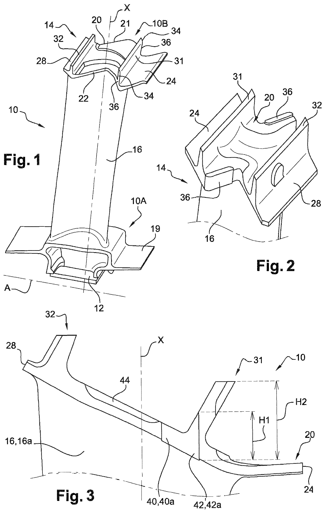
[0036]The invention applies to a movable wheel vane 10 as described above with reference to FIGS. 1 and 2.

[0037]The vane 10 comprises at least one blade 16 which extends between two platforms, respectively internal 19 and external 20. The internal platform 19 is connected to the radially internal end of the blade and the external platform 20 is connected to the radially external end of the blade and comprises coverings 36 of wear-resistant material.

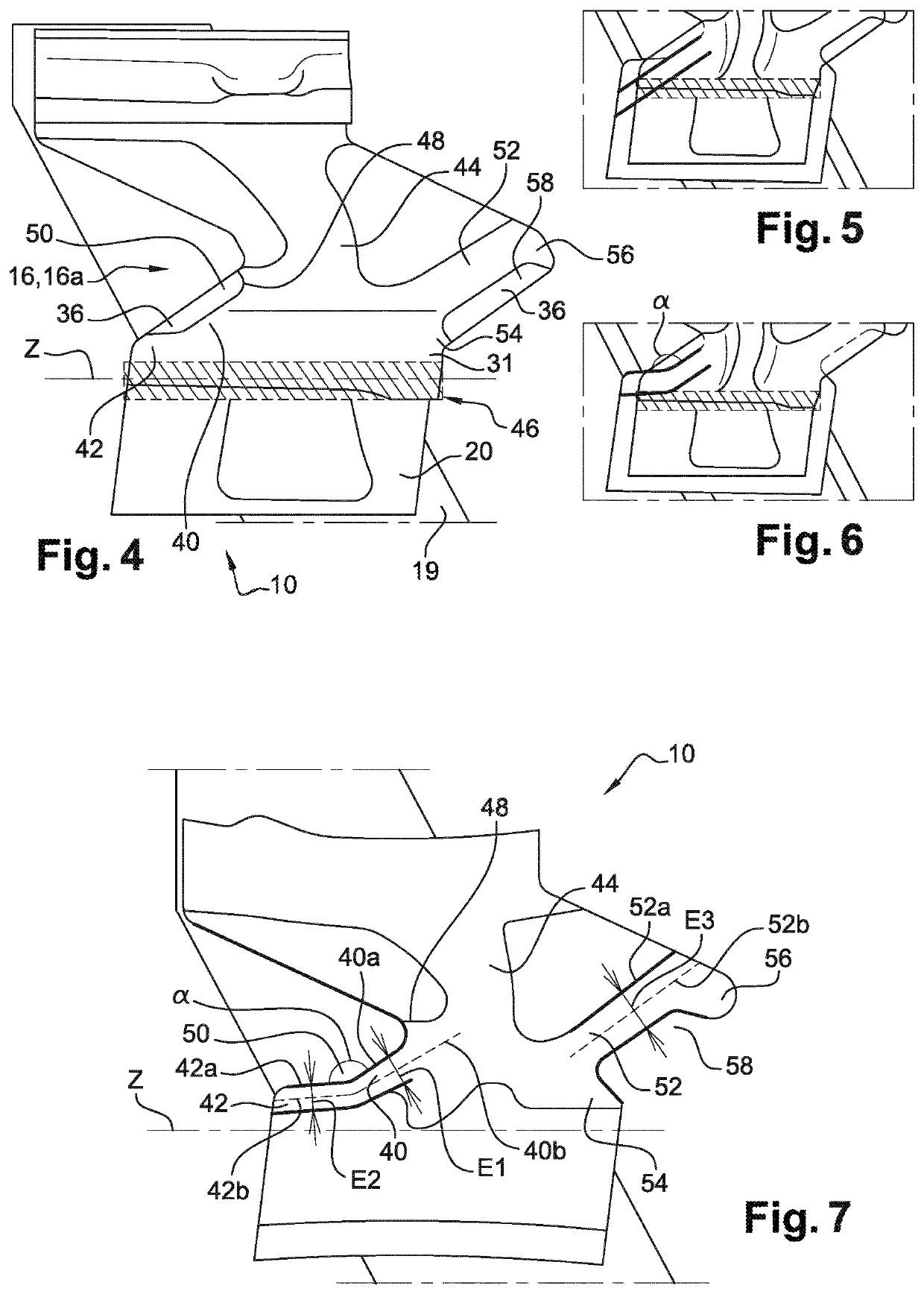
[0038]FIGS. 3, 4, 6 and 7 illustrate an embodiment of the invention.

[0039]According to the invention, the wear-resistant covering 36 of the lateral edge 22 located on the side of the pressure side 16a of the blade 16 extends on a wall 40a of a first ridge 40 which is located between the lips 31, 32, and on a wall 42a of a second ridge 42 which extends at least partly into the lip 31. The ridges 40, 42 are an integral part of the platform 20. As can be seen in FIG. 3, the wall 42a extends over approximately 20-50% of the height of the lip ...


PUM


Abstract

The invention relates to a rotor vane (10) for an aircraft turbine engine, said vane having an axis (A) of rotation once it has been rigidly connected to a rotor and a stacking axis (X). The vane comprises a blade (16) extending between an internal platform (19) and an external platform (20) bearing at least one projecting lip (31, 32), said blade having a lower surface (16a) and an upper surface (16b). The external platform comprises lower (22) and upper (21) side edges, located on the side of the lower (16a) and upper (16b) surfaces respectively and configured to cooperate in a form-fitting manner with the complementary side edges (21, 22) of adjacent vanes, each of said side edges having a wear-resistant covering (36). The rotor vane of the invention is characterised in that the wear-resistant covering of the lower side edge extends over one wall (40a) of a substantially rectilinear first ridge (40) of the platform and over one wall (42a) of a second ridge (42) of the platform, said second ridge extending at least partially inside the lip (31) and being inclined relative to the first ridge in a direction substantially parallel to a transverse axis (Z) of the lip.

Description

TECHNICAL FIELD[0001]The present invention relates to the general field of the manufacture of rotor vanes for an aircraft turbomachine.BACKGROUND[0002]The prior art comprises in particular document FR-A1-2 985 759.[0003]Typically, an axial turbine in a turbomachine consists of a series of axial stages (along the axis of circulation of the gas flow) arranged in series. Each stage comprises a movable wheel with vane forming a rotor and a bladed distributor forming a stator. The movable wheel is rotated opposite the corresponding distributor.[0004]In this patent application, the upstream and downstream are defined in relation to the normal flow direction of the air flows (upstream to downstream) through the turbomachine. The axis of rotation of the main rotor of the turbomachine is referred to as the “axis of the turbomachine”. The axial direction is the direction of the axis of the turbomachine, and a radial direction is a direction perpendicular to the axis of the turbomachine and in...

Claims


Application Information

Patent Timeline
Patent Type & Authority Applications(United States)
IPC IPC(8): F01D5/28
CPCF05D2240/24F05D2220/323F01D5/288F01D5/225
Inventor LOISEL, BRUNO MARC-ETIENNEDEFLANDRE, STEPHANIE ALINE MARIEDELCOIGNE, ERIC JACQUESLIMOUSIN, FRANCK DENIS DANIELPERSON, LAETITIA NICOLE
Owner SN DETUDE & DE CONSTR DE MOTEURS DAVIATION S N E C M A
Why Eureka
Try Eureka