Valve clamping device and valve repairing system

A clamp and valve technology, applied in the field of medical equipment, can solve the problems of poor clamping effect of the valve clamp

Pending Publication Date: 2022-03-15
BEIJING LINGJIAN MEDICAL TECH CO LTD
View PDF0 Cites 1 Cited by
  • Summary
  • Abstract
  • Description
  • Claims
  • Application Information

AI Technical Summary

Problems solved by technology

[0005] The purpose of the present invention is to at lea...

Method used


Image

  • Valve clamping device and valve repairing system
  • Valve clamping device and valve repairing system
  • Valve clamping device and valve repairing system

Examples


Embodiment Construction

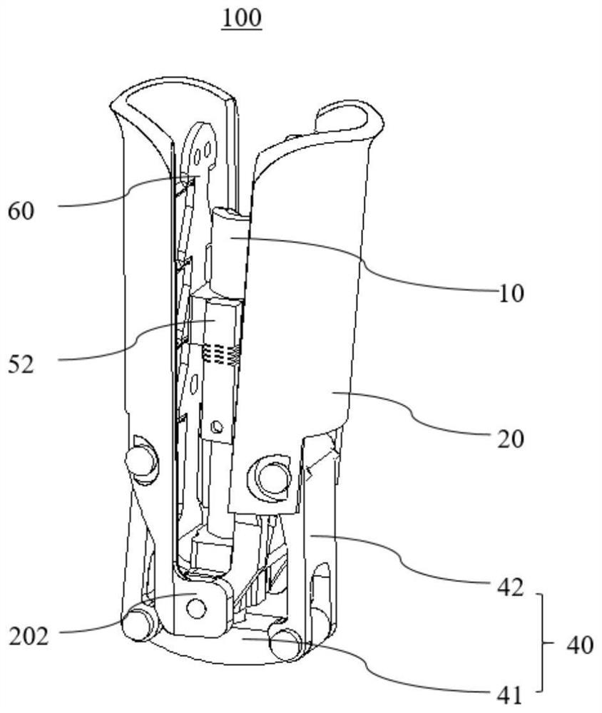
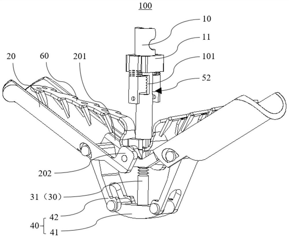
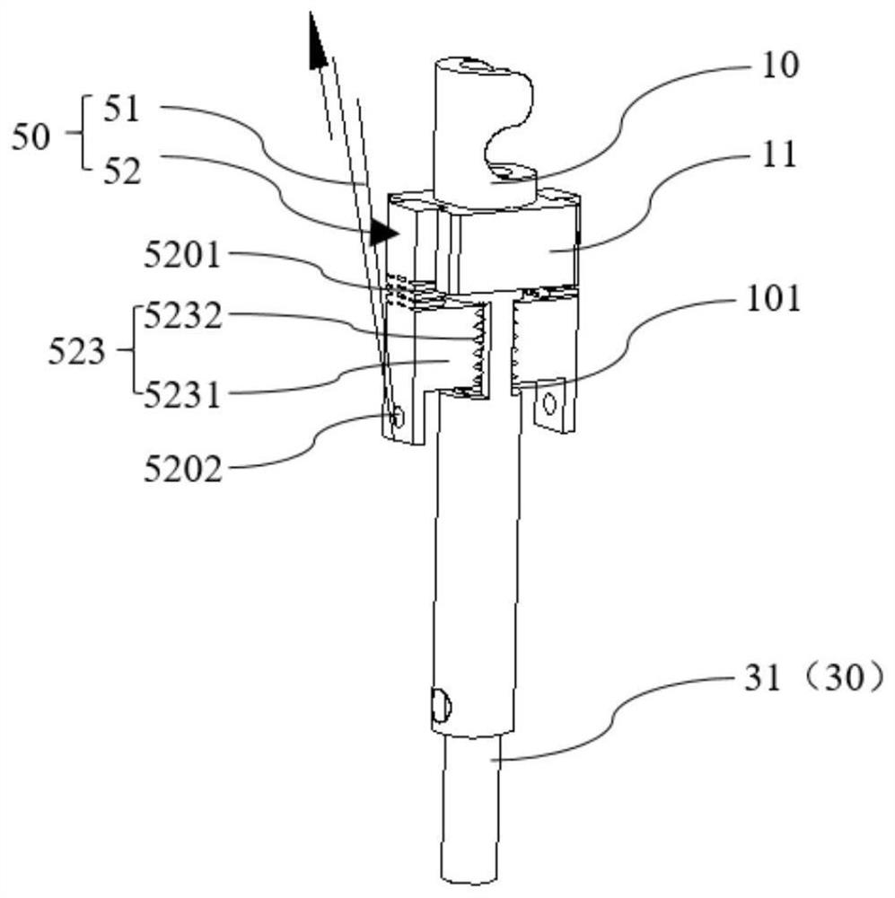
[0046] As mentioned in the background technology, taking mitral valve repair surgery as an example, after the clamp arm of the valve clamp clamps the valve, it needs to be locked, that is, to prevent the clamp arm from rotating and unfolding. In some existing valve clamps, the lock The locking mechanism consists of multiple parts, and because the volume of the valve clamp is limited as an implant, the overall axial dimension of the valve clamp is generally less than 16mm, so when multiple components are used to achieve locking, the locking mechanism It will occupy a relatively large axial space, resulting in a corresponding reduction in the axial dimension of the clamp arm, which will affect the clamping effect of the clamp arm. In view of the above problems, the present invention proposes a valve clamp and a valve repair system. The valve clamp is provided with a locking elastic piece, the side wall of the central shaft cylinder is provided with a window, and the clips on the ...


PUM


Abstract

The invention relates to a valve clamping device and a valve repairing system.The valve clamping device comprises a center shaft barrel, a sliding component, a locking mechanism and a plurality of clamping arms, and a window is formed in the side wall of the center shaft barrel; the plurality of clamping arms are wound on the periphery of the central shaft barrel; the sliding component is arranged in the central shaft barrel in a sliding mode, the sliding component is connected with the clamping arms through a pivoting mechanism so that the clamping arms can rotate according to axial sliding of the sliding component, and a clamping part is arranged on the side wall of the sliding component; the locking mechanism comprises a control component and a locking elastic piece, the locking elastic piece is provided with a movable section and a fixed section connected to the center shaft barrel, a clamping piece is arranged on the locking elastic piece and stretches into the window to be connected with the clamping part in a clamped mode, and the control component is connected with the locking elastic piece and can control the clamping piece to be away from the clamping part to relieve clamping. According to the valve clamping device, the locking mechanism does not additionally occupy the axial space, the clamping arms of the valve clamping device can be conveniently lengthened, and the clamping effect is improved.

Description

technical field [0001] The invention belongs to the technical field of medical devices, and in particular relates to a valve clamp and a valve repair system. Background technique [0002] Heart valve refers to the valve between the atrium and the ventricle or between the ventricle and the artery. The atrioventricular valve includes the mitral valve and the tricuspid valve. The mitral valve is two valves attached to the periphery of the left atrioventricular orifice and connected to the nipple by the tendon Mitral valve regurgitation is a poor anastomosis of the anterior and posterior leaflets of the mitral valve caused by organic or functional changes in the mitral valve leaflets and related structures. During valve regurgitation, the blood flow will flow back from the left ventricle to the left atrium, causing a series of pathophysiological changes. [0003] Surgical valve repair or replacement is considered to be the standard treatment for this type of disease. However, s...

Claims


Application Information

Patent Timeline
IPC IPC(8): A61F2/24
CPCA61F2/2466A61F2/246A61F2/2442A61F2/2436A61F2210/0014
Inventor 张军傲谢晨光周晓军马为
Owner BEIJING LINGJIAN MEDICAL TECH CO LTD
Why Eureka
Try Eureka