Automatic plate cutting device capable of fixing distance

A cutting device and fixed-distance technology, which is applied in the field of fixed-distance automatic plate cutting devices, can solve the problems of unusable plates and excessive cutting of plates, and achieve the effect of increasing the degree of automation and improving work efficiency

Active Publication Date: 2022-04-01
深圳亚士德科技有限公司
View PDF7 Cites 1 Cited by
  • Summary
  • Abstract
  • Description
  • Claims
  • Application Information

AI Technical Summary

Problems solved by technology

[0005] In order to overcome the existing fixed-distance cutting device for wood board processing, the cutting piece rotates and stops by turning on and off the power. Excessive cutting, which makes the board unusable, provides a fixed-distance automatic board cutting device that has a good effect on the fixed-distance cutting of the board and automatically performs the cutting work.

Method used


Image

  • Automatic plate cutting device capable of fixing distance
  • Automatic plate cutting device capable of fixing distance
  • Automatic plate cutting device capable of fixing distance

Examples


Embodiment 1

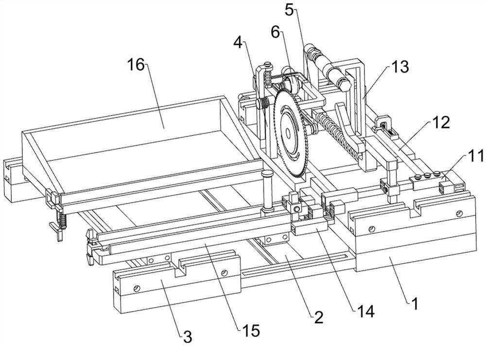
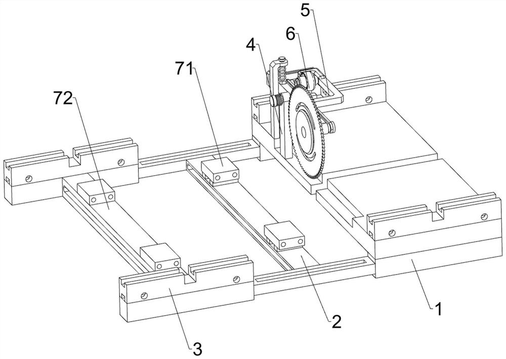
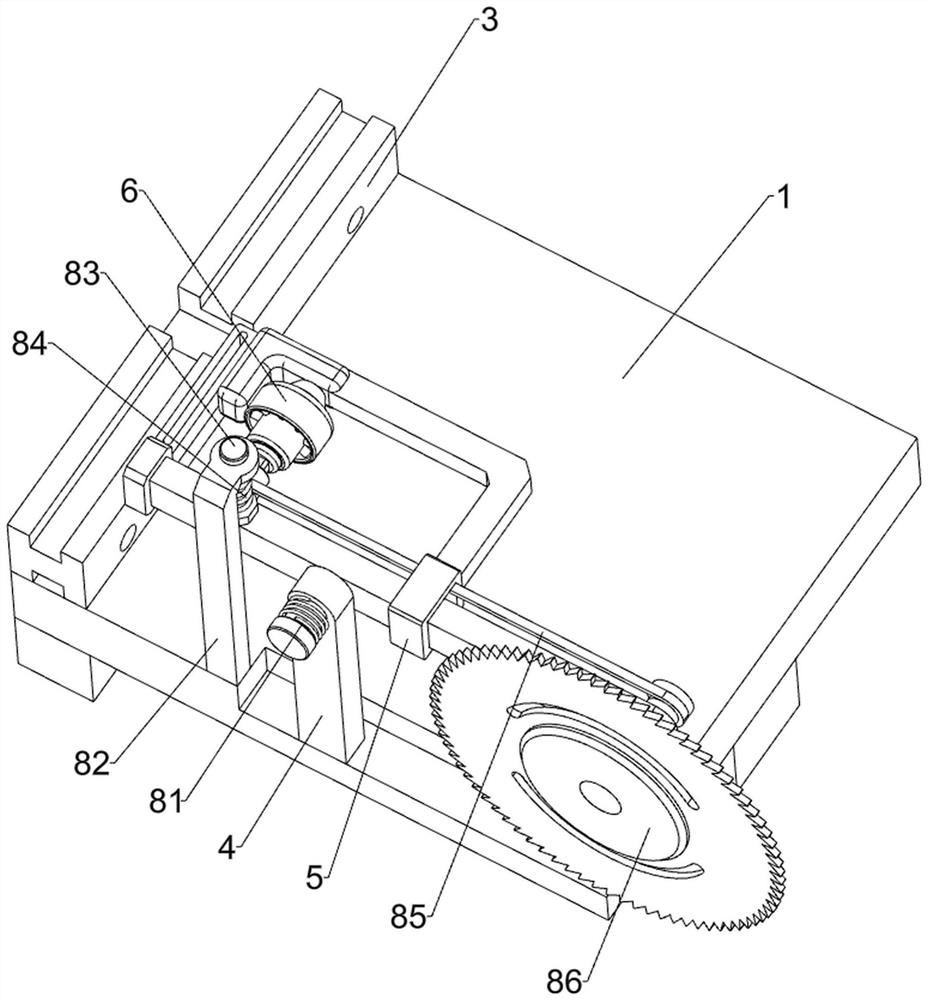
[0036] An automatic plate cutting device with fixed distance, refer to Figure 1-9 As shown, it includes a mounting frame 1, a connecting frame 2, a guide plate 3, a mounting plate 4, a stabilizing frame 5, a servo motor 6, a support block 71, a support plate 72, a first spring 81, a buffer frame 82, a buffer rod 83, Second spring 84, belt 85, cutting wheel 86, fixed distance mechanism 11, adjustment mechanism 12 and hold-down mechanism 13, connecting frame 2 right sides are provided with mounting frame 1 by the mode of welding front and rear symmetry, rear side mounting frame 1 top left The side is provided with a mounting plate 4 by welding, the upper side of the mounting plate 4 is rotatably provided with a stabilizer 5, the rear side of the stabilizer 5 is provided with a servo motor 6, and the right side of the top of the connecting frame 2 is provided with a symmetrical front and rear support by welding Block 71, the left side of the connecting frame 2 is provided with a...

Embodiment 2

[0042] On the basis of embodiment 1, refer to figure 1 with Figure 10 As shown, an anti-jamming mechanism 14 is also included, and the anti-jamming mechanism 14 further limits the plate. Three screws 145, the lower part of the front side of the second bracket 117 is provided with an anti-jamming plate 141 by welding, the rear left part of the anti-jamming plate 141 is provided with a splicing block 142 by welding, and the front side of the top of the splicing block 142 is welded The third sliding rod 143 is provided in the way, and the anti-jamming rod 144 is slid on the third sliding rod 143. The anti-jamming rod 144 can further limit the plate, and the front side of the anti-jamming rod 144 is threaded with a third screw. 145.

[0043]When putting the plate, the staff can also turn the third screw 145 away from the anti-seize bar 144, so that the anti-seize bar 144 is unclamped, and then adjust the anti-seize bar 144 at the position of the third slide bar 143 according to...


PUM


Abstract

The invention relates to a plate cutting device, in particular to a fixed-distance automatic plate cutting device. The automatic plate cutting device capable of achieving the fixed distance is good in plate fixed distance cutting effect and capable of automatically conducting cutting work. According to the technical scheme, the fixed-distance automatic plate cutting device comprises mounting frames, a connecting frame, a mounting plate, a stabilizing frame, a servo motor, a supporting block, a supporting plate and the like, the mounting frames are symmetrically arranged on the right side of the connecting frame front and back, the mounting plate is arranged on the left side of the top of the mounting frame on the rear side, and the stabilizing frame is rotationally arranged on the upper side of the mounting plate; supporting blocks are symmetrically arranged on the right side of the top of the connecting frame front and back, and a supporting plate is arranged on the left side of the connecting frame. And the position of the top sleeve is adjusted, so that the plate can be cut into the required length, and the fixed-distance cutting work of the plate can be realized.

Description

technical field [0001] The invention relates to a plate cutting device, in particular to an automatic plate cutting device with a fixed distance. Background technique [0002] Before the plate is used, the plate is often processed and then used. If the plate needs to be cut with high precision, it is necessary to measure the distance before cutting, which will reduce the processing efficiency of the plate. [0003] The patent application number is CN201921975349.1, which discloses a fixed-distance cutting device for wood board processing, including supporting legs, the top of the supporting legs is fixedly connected to the bottom surface of the work box, and the middle part of the front of the work box is fixedly connected with a scale bar. The bottom surface of the inner cavity of the work box is provided with a strip groove, and the middle and right sides of the strip groove are respectively clamped with a pointer and a conductive block, and the middle part of the pointer ...

Claims


Application Information

Patent Timeline
Patent Type & Authority Applications(China)
IPC IPC(8): B27C5/02B27C5/06
Inventor 李冬杨小强刘永裕
Owner 深圳亚士德科技有限公司
Why Eureka
Try Eureka