
Lens, optical system and lamp
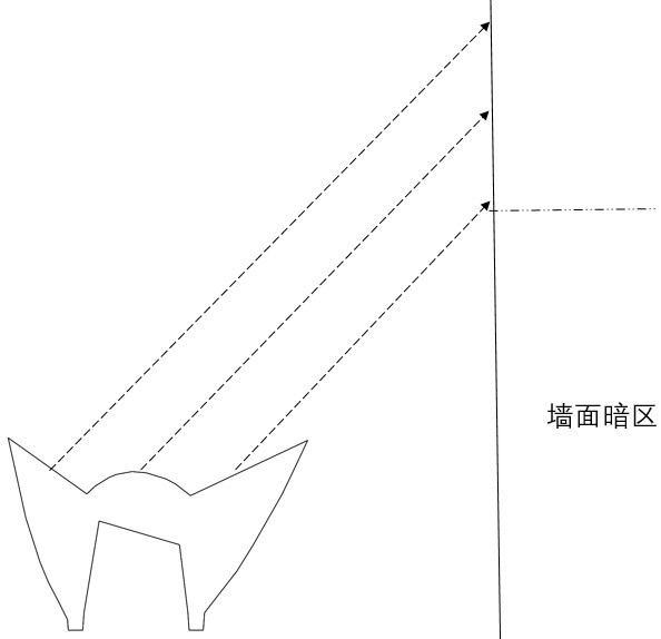
An optical system and lens technology, applied to lighting devices, components of lighting devices, refractors, etc., can solve problems such as glare and severe glare, and achieve the effects of weak direct glare, elimination of dark areas, and comfortable visual effects
- Summary
- Abstract
- Description
- Claims
- Application Information
AI Technical Summary
Problems solved by technology
Method used
Image

Examples
Embodiment Construction
[0025] The following detailed description of the present invention is further described below with reference to the accompanying drawings and specific embodiments.
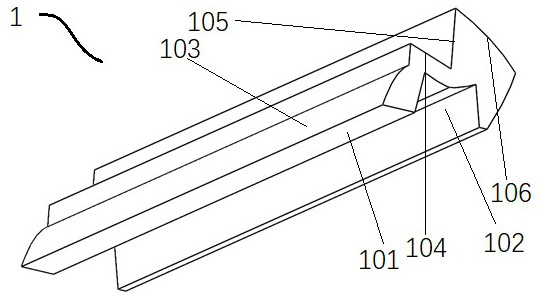
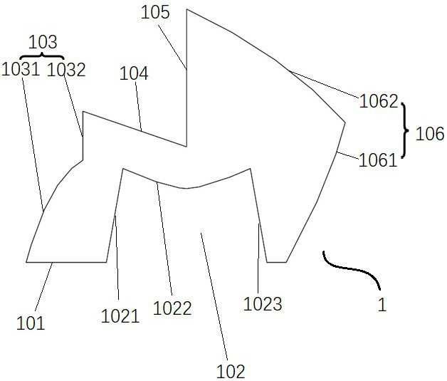
[0026] The structure of the lens 1 of the present application, such as figure 2 As shown, the lens 1 is a stretching lens, image 3 The cross section is stretched in line straight. The lens 1 includes a bottom surface 101, and the bottom surface 101 is formed into a light receiving chamber 102 by a depression, which can be used to accommodate the light source. The enample cavity 42 includes a first incident surface 1021, a second incident surface 1022, a third into the optical surface 1023. Wherein, the first incident surface 1021, the third entrance surface 1023 is connected to the plane and the bottom surface 101, respectively. The second incident surface 1022 is a curved surface protruding from the lens 1, and the curved surface may be a circular arc surface or a free surface. In other preferred embodiments, the inf...
PUM
 Abstract
Description
Claims
Application Information