Supercharge Your Innovation With Domain-Expert AI Agents!

Safety height limiting device for hoisting machinery

A technology of hoisting machinery and limit devices, applied in safety devices, transportation and packaging, load hanging components, etc., can solve problems such as easy detachment and looseness, and achieve the effects of simple operation, convenient limit buffering, and convenient use

Pending Publication Date: 2022-04-12
烟台市特种设备检验研究院
View PDF0 Cites 0 Cited by
  • Summary
  • Abstract
  • Description
  • Claims
  • Application Information

AI Technical Summary

Problems solved by technology

[0004] The purpose of the present invention is to solve the shortcoming that the steel rope on the existing crane will loosen temporarily due to inertia when it is at a standstill, so that it is easy to break away from the connection with the guide wheel, and proposes a safety height limit for hoisting machinery. bit device

Method used


Image

  • Safety height limiting device for hoisting machinery
  • Safety height limiting device for hoisting machinery
  • Safety height limiting device for hoisting machinery

Examples


Embodiment 1

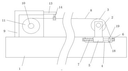
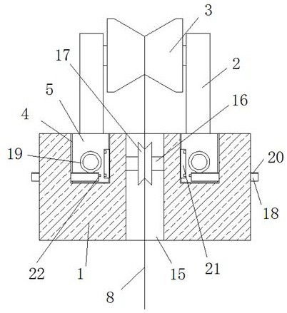
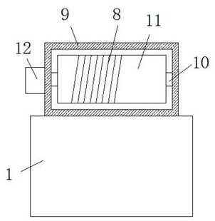
[0023] refer to Figure 1-5 , a safety height limiting device for hoisting machinery, comprising a fixed rod 1, the top of the fixed rod 1 is slidably connected with two symmetrically arranged positioning plates 2, and a positioning shaft is rotationally connected between the two positioning plates 2, and on the positioning shaft A guide wheel 3 is fixedly installed, and a steel rope 8 is connected to the guide wheel 3. A winding mechanism is provided on the fixed rod 1, and the winding mechanism cooperates with the steel rope 8. It is connected with the transmission of two positioning plates 2, and the fixed rod 1 is provided with a through hole 15, and the inner wall of the through hole 15 is rotatably connected with a transmission shaft 16, and a transmission wheel 17 is fixedly installed on the transmission shaft 16, and the transmission wheel 17 and the steel rope 8 Transmission connection, the transmission shaft 16 is provided with a clipping mechanism, and the clipping ...

Embodiment 2

[0028] refer to Figure 1-5 , a safety height limiting device for hoisting machinery, comprising a fixed rod 1, the top of the fixed rod 1 is slidably connected with two symmetrically arranged positioning plates 2, and a positioning shaft is rotationally connected between the two positioning plates 2, and on the positioning shaft A guide wheel 3 is welded, and a steel rope 8 is connected to the guide wheel 3. The fixed rod 1 is provided with a winding mechanism, which cooperates with the steel rope 8. The top of the fixed rod 1 is provided with a buffer mechanism. The two positioning plates 2 are connected by transmission, the fixed rod 1 is provided with a through hole 15, the inner wall of the through hole 15 is connected with a transmission shaft 16, and the transmission shaft 16 is welded with a transmission wheel 17, and the transmission wheel 17 is connected with the steel rope 8 , The drive shaft 16 is provided with a clamping mechanism, and the clamping mechanism is in...


PUM


Abstract

The invention belongs to the technical field of cranes, particularly relates to a safety height limiting device for hoisting machinery, and provides the following scheme aiming at the problem that a steel rope on the existing crane is easily separated from a guide wheel due to transient looseness caused by inertia effect when the steel rope is paused: the safety height limiting device comprises a fixed rod, the top of the fixing rod is slidably connected with two symmetrically-arranged positioning plates, a positioning shaft is rotationally connected between the two positioning plates, a guide wheel is fixedly installed on the positioning shaft, a steel rope is in transmission connection with the guide wheel, a winding mechanism is arranged on the fixing rod, the winding mechanism is matched with the steel rope, and the steel rope is fixedly connected with the positioning shaft. A buffering mechanism is arranged at the top of the fixing rod and is in transmission connection with the two positioning plates, and a through hole is formed in the fixing rod. The device is easy to operate and convenient to use, the steel rope can be conveniently limited and buffered when being stopped, meanwhile, the steel rope can be conveniently positioned and wound, and people can conveniently use the device.

Description

technical field [0001] The invention relates to the technical field of cranes, in particular to a safety height limiting device for a crane. Background technique [0002] Hoisting machinery is a kind of engineering machinery capable of lifting, transporting and loading and unloading materials, and is widely used in lifting and hoisting operations in construction sites, ports, oil fields, railways, warehouses, wind power and other working conditions. Specifically, such as building bridges, installing power generation equipment, shipbuilding, erecting wind turbines, etc. In recent years, with the rapid development of the national economy, cranes have played an increasingly important role in many industries. Hoisting machinery has become an important tool to reduce labor intensity and improve production efficiency, and people pay more and more attention to the improvement of crane performance. [0003] The steel rope on the existing crane will loosen temporarily due to inerti...

Claims


Application Information

Patent Timeline
Patent Type & Authority Applications(China)
IPC IPC(8): B66C15/00B66C13/00
Inventor 赵西城李培峨董军
Owner 烟台市特种设备检验研究院
Features
  • R&D
  • Intellectual Property
  • Life Sciences
  • Materials
  • Tech Scout
  • Unparalleled Data Quality
  • Higher Quality Content
  • 60% Fewer Hallucinations
Learn More