Chip manufacturing protective gas flow control device

A technology of flow control device and shielding gas, which is applied in the direction of manufacturing tools, auxiliary devices, welding equipment, etc., and can solve the problem of disconnection of the connection end between the pipeline and the welding robot

Active Publication Date: 2022-05-27
CHONGQING COLLEGE OF ELECTRONICS ENG
View PDF10 Cites 0 Cited by
  • Summary
  • Abstract
  • Description
  • Claims
  • Application Information

AI Technical Summary

Problems solved by technology

[0005] The purpose of the present invention is to provide a protective gas flow control device for chip manufacturing, which aims to solve the problem that the vibration generated when the protective gas flows in the pipeline will cause the pipeline to disconnect from the connection end of the welding robot

Method used


Image

  • Chip manufacturing protective gas flow control device
  • Chip manufacturing protective gas flow control device
  • Chip manufacturing protective gas flow control device

Examples


Embodiment Construction

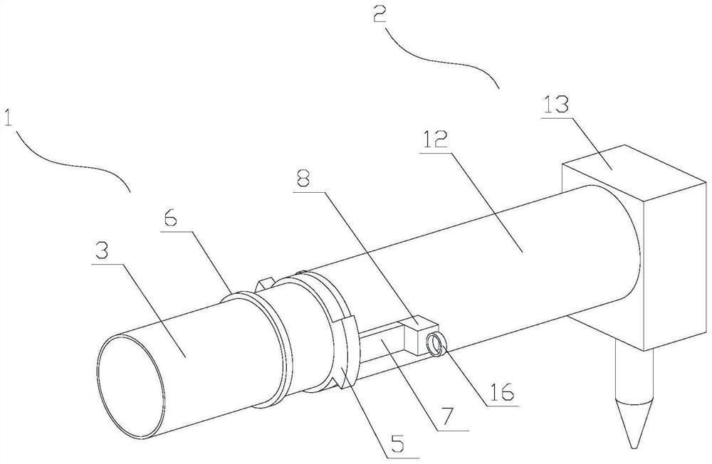
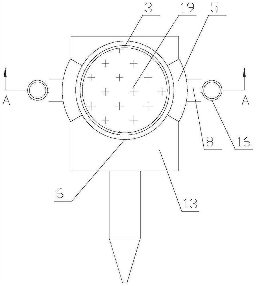
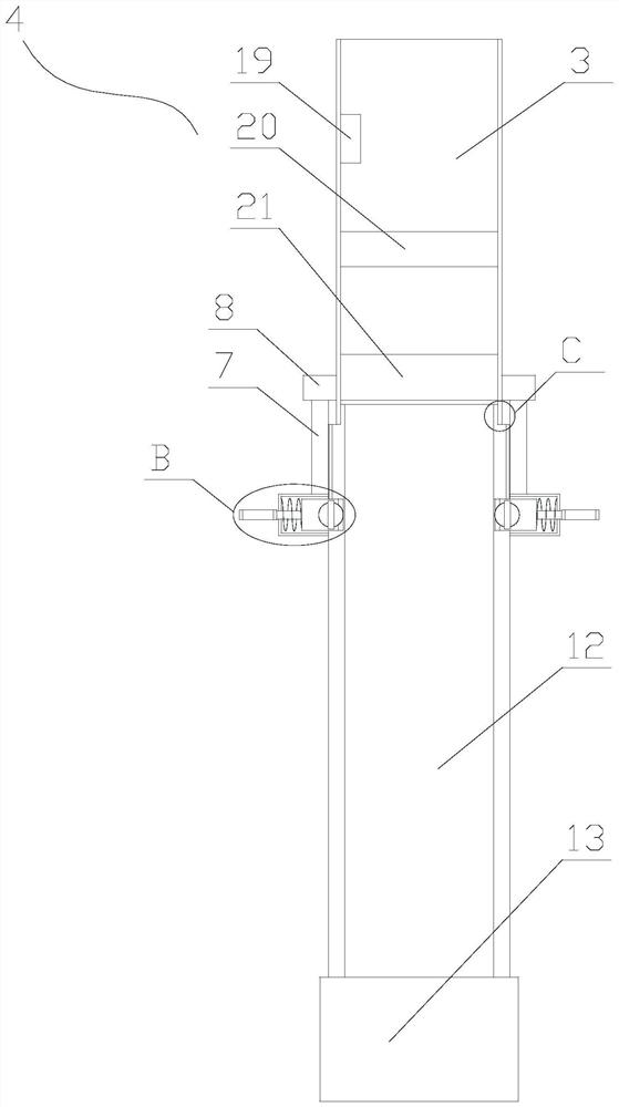
[0023] The following describes in detail the embodiments of the present invention, examples of which are illustrated in the accompanying drawings, wherein the same or similar reference numerals refer to the same or similar elements or elements having the same or similar functions throughout. The embodiments described below with reference to the accompanying drawings are exemplary, and are intended to explain the present invention and should not be construed as limiting the present invention.

[0024] In the description of the present invention, it should be understood that the terms "length", "width", "upper", "lower", "front", "rear", "left", "right", "vertical", The orientations or positional relationships indicated by "horizontal", "top", "bottom", "inside", "outside", etc. are based on the orientations or positional relationships shown in the drawings, which are only for the convenience of describing the present invention and simplifying the description, rather than An ind...


PUM


Abstract

The invention relates to the technical field of metal processing devices, in particular to a chip manufacturing protective gas flow control device which comprises a flow control mechanism and a welding robot. The flow control mechanism comprises a pipeline, a control assembly, a mounting ring, two limiting rings, two supporting rods, two sliding grooves, two abutting blocks, two reset springs and two sliding assemblies, the welding robot comprises a connecting pipe and a welding assembly, the connecting pipe is provided with two clamping grooves, and the connecting pipe is connected to the inner side wall of the pipeline through threads; the mounting ring slides on the pipeline to drive the abutting block to slide on the outer side wall of the connecting pipe through the sliding assembly until the sliding assembly drives the abutting block to enter the clamping groove, so that the connecting pipe is clamped on the pipeline, and the problem that the pipeline is disconnected from the connecting end of the welding robot due to vibration generated when protective gas flows in the pipeline is solved.

Description

technical field [0001] The present invention relates to the technical field of metal processing devices, in particular to a device for controlling the flow of protective gas in chip manufacturing. Background technique [0002] Welding is one of the important steps in the chip manufacturing process. During welding, the flow of shielding gas also plays an important role. The key purpose of shielding gas used in the welding process is to protect the molten pool. The flow of shielding gas is controlled by the flow of shielding gas. device to control. [0003] At present, the prior art (CN202571550U) discloses a muffler welding shielding gas flow control device, which includes a first flow meter, a pressure regulating valve, a pipeline, a solenoid valve, a welding robot and a PLC control unit. A first flow meter, a pressure regulating valve and a solenoid valve are sequentially installed on the pipeline, and the outlet of the pipeline is connected with the welding robot. The so...

Claims


Application Information

Patent Timeline
Patent Type & Authority Applications(China)
IPC IPC(8): F16L27/12B23K3/08
CPCF16L27/12B23K3/08Y02P70/10
Inventor 林涛李志贵杨毓军马岗强
Owner CHONGQING COLLEGE OF ELECTRONICS ENG
Why Eureka
Try Eureka