Miniaturized dual-frequency antenna

A dual-frequency antenna and frequency technology, applied in antennas, resonant antennas, antenna components, etc., can solve problems such as narrow frequency band bandwidth, reduced radiation efficiency, and increased antenna structure, and achieve widened antenna bandwidth, high radiation efficiency, and antenna small size effect

Pending Publication Date: 2022-07-05
MICRONET UNION TECH (CHENGDU) CO LTD
View PDF0 Cites 0 Cited by
  • Summary
  • Abstract
  • Description
  • Claims
  • Application Information

AI Technical Summary

Problems solved by technology

Antennas loaded with slots are generally difficult to achieve broadband matching in high frequency bands, and cannot cover Wi-Fi6 or Wi-Fi6E frequency bands, resulting in low radiation efficiency
[0005] As far as the commonly used UWB antennas are concerned, UWB monopole antennas are generally used, which have the advantage of wide bandwidth and do not need to consider the problem of frequency offset. However, UWB monopole antennas generally have a large size and require a large Otherwise, there will be current on the feed line that will shift the pattern and may flow into the circuit to affect the chip's work.
[0006] As far as the commonly used all-metal dual-band Wi-Fi antennas are concerned, they are generally processed by laser cutting of metal sheets. The deviation will degrade the performance, especially when the bandwidth is narrow, the frequency deviation will increase and reduce the radiation efficiency, and may also affect the output port of the RF chip
[0007] In addition, as far as the current dual-band implementation method is concerned, multi-twig antennas will lead to an increase in the antenna structure, which is not conducive to the use of small-sized devices
Using a matching circuit to achieve dual frequency generally matches a narrow frequency band, and is prone to frequency deviation due to device tolerances

Method used


Image

  • Miniaturized dual-frequency antenna
  • Miniaturized dual-frequency antenna
  • Miniaturized dual-frequency antenna

Examples


Embodiment 1

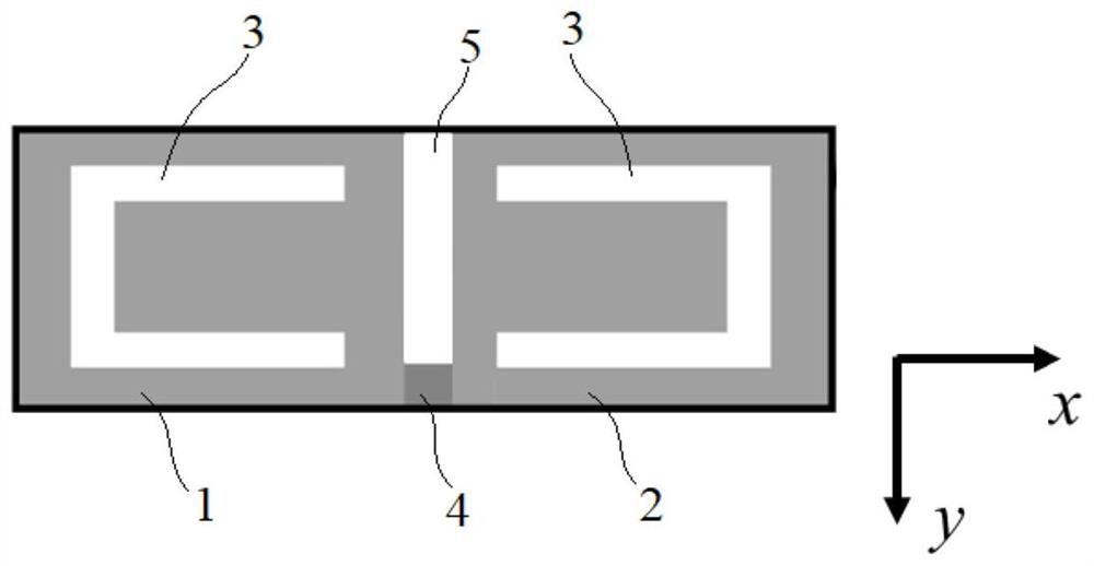
[0042] see figure 1 As shown, as an embodiment of a miniaturized dual-frequency antenna, it includes a first dipole arm 1 and a second dipole arm 2 that are symmetrical to each other, the first dipole arm 1 and the second dipole arm 1 The dipole formed by the sub-arm 2 is used to generate the first resonance point;

[0043] The first dipole arm 1 and the second dipole arm 2 respectively have a first U-shaped slot 3, the two first U-shaped slots 3 are symmetrical with each other and the openings are opposite to each other, the first U-shaped slot 3 for generating a second resonance point, the frequency of the first resonance point is different from the frequency of the second resonance point;

[0044] The two ends of the first dipole arm 1 and the second dipole arm 2 that are close to each other are respectively connected to the feeding structure 4. Optionally, the feeding structure 4 can be configured as a feeding metal sheet, or a For the feeding port, it is sufficient to c...

Embodiment 2

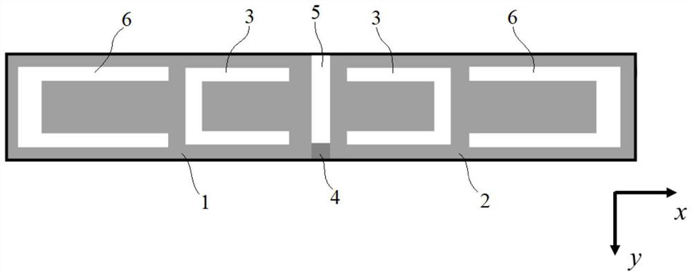
[0049] pass Figure 5 For the simulated reflection coefficient test results of the antenna of Example 1, it can be found that although the antenna of Example 1 has improved high-band bandwidth compared to the existing Wifi dual-band antenna, it still cannot form a better performance for 5-7.125GHz. coverage. Based on this, see figure 2 As shown, on the basis of Embodiment 1, as a further improvement solution, in the miniaturized dual-frequency antenna of this embodiment, the first dipole arm 1 and the second dipole arm 2 have one The second U-shaped groove 6, the two second U-shaped grooves 6 are symmetrical with each other and the openings are opposite to each other, the second U-shaped groove 6 and the first U-shaped groove 3 are located on the same axis; Specifically, the two first U-shaped grooves 3 and two second U-shaped grooves 6 to form a linear arrangement in the X-axis direction, the second U-shaped groove is located on one side of the vertical groove section of t...

Embodiment 3

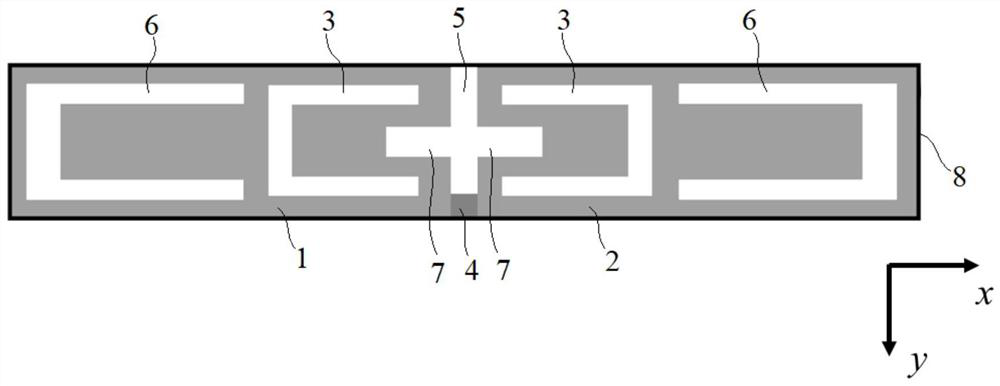
[0054] pass Figure 5 For the simulated reflection coefficient test results of the antenna of Example 2, it can be found that although the high-frequency bandwidth of the antenna of Example 2 has been further widened relative to the dual-band antenna of Example 1, it still cannot satisfy the requirements for Wi-Fi - Higher frequency band bandwidth requirements proposed by Fi6 or Wi-Fi6E frequency bands. Based on this, see image 3 As shown, on the basis of Embodiment 2, as a further improvement solution, in the miniaturized dual-frequency antenna of this embodiment, the first dipole arm 1 and the second dipole arm 2 are close to each other. The two ends are respectively provided with a straight groove 7, and the two straight grooves 7 form a vertical orthogonal relationship with the gap 5 between the first dipole arm 1 and the second dipole arm 2; the straight grooves 7 is used to generate a fourth resonance point, and the frequency of the fourth resonance point is different...


PUM


Abstract

The invention provides a miniaturized dual-band antenna, which comprises a first dipole arm and a second dipole arm which are symmetrical to each other, and a dipole formed by the first dipole arm and the second dipole arm is used for generating a first resonance point; the first dipole arm and the second dipole arm are respectively provided with a first U-shaped groove, the two first U-shaped grooves are mutually symmetrical, openings of the two first U-shaped grooves are opposite, the first U-shaped grooves are used for generating a second resonance point, and the frequency of the first resonance point is different from that of the second resonance point; the two ends, close to each other, of the first dipole arm and the second dipole arm are connected with the feed structure. According to the dual-frequency antenna, a novel dual-frequency structure is adopted, a plurality of slot combinations can be loaded to realize broadband matching at a high frequency band, meanwhile, the dual-frequency antenna has the advantages of miniaturization and high radiation efficiency, and the requirement of a Wifi 6E frequency band can be well met.

Description

technical field [0001] The present invention relates to an antenna in a wireless communication system, in particular to a miniaturized dual-frequency antenna. Background technique [0002] Antenna is an indispensable and important component in wireless communication systems and radar systems. The performance of the antenna determines the performance and quality of the entire wireless system. With the comprehensive advancement of wireless communication technologies represented by 5G and the Internet of Things, there is an urgent need to develop high-quality antenna components suitable for their application scenarios. Wi-Fi antennas are widely used in wireless communication systems, and the demand is very large, especially for low-cost, high-efficiency miniaturized dual-band Wi-Fi antennas. At present, the commonly used Wi-Fi antennas are mainly monopoles and dipoles, including all-metal structures and printed circuit board structures. In addition, the dual-band PIFA antenna...

Claims


Application Information

Patent Timeline
Patent Type & Authority Applications(China)
IPC IPC(8): H01Q5/20H01Q5/10H01Q5/50H01Q9/30H01Q1/38H01Q1/48H01Q1/22H01Q1/00
CPCH01Q5/20H01Q5/10H01Q5/50H01Q1/38H01Q1/48H01Q1/002H01Q9/30H01Q1/2291
Inventor 董元旦陈涛程洋黄春生程华灼冯燕坡刘梦雅田忠
Owner MICRONET UNION TECH (CHENGDU) CO LTD
Why Eureka
Try Eureka