Bus duct power distribution system and bus duct production process

A power distribution system and busbar technology, applied in cooling busbar devices, fully enclosed busbar devices, etc., can solve the problems of poor heat dissipation capacity of busbar conductors, low current carrying capacity of conductors, and poor mechanical strength, etc., to improve ventilation and heat dissipation. effect, reducing heat build-up, increasing mechanical strength and the effect of ductile surfaces

Pending Publication Date: 2022-07-08
深圳市爱得威母线制造有限公司
View PDF0 Cites 0 Cited by
  • Summary
  • Abstract
  • Description
  • Claims
  • Application Information

AI Technical Summary

Problems solved by technology

[0003] The busway in the related art is composed of a product structure shell and a conductor. The conductor of the busway is a rectangular solid conductor. The solid structure of the conductor makes the extension surface too small, resulting in a relatively low current-carrying capacity of the conductor, low protection level, and poor mechanical strength. , prone to heat accumulation
[0004] In view of the related technologies mentioned above, the conductor of the busway has the defect of poor heat dissipation

Method used


Image

  • Bus duct power distribution system and bus duct production process
  • Bus duct power distribution system and bus duct production process
  • Bus duct power distribution system and bus duct production process

Examples


Embodiment 1

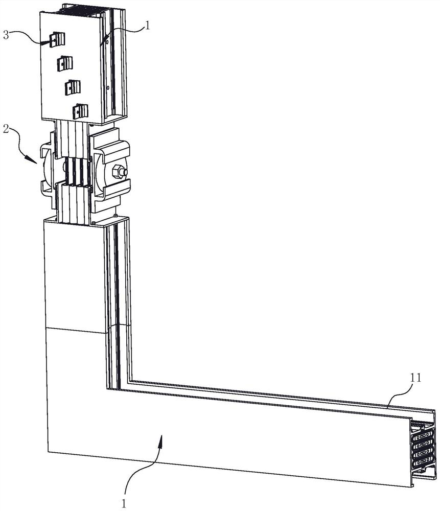
[0054] The embodiment of the present application discloses a busbar trunking power distribution system. refer to figure 1 , a bus duct power distribution system includes a plurality of interconnected bus ducts 1, a connector 2 for connecting the bus duct 1, and a connector 3 for electrically connecting the bus duct 1 with external equipment. The connector 2 can By connecting two busbar ducts 1 separated from each other, the current of the busbar duct 1 can be connected to an external device through the plug connector 3, so as to supply power to the external device.

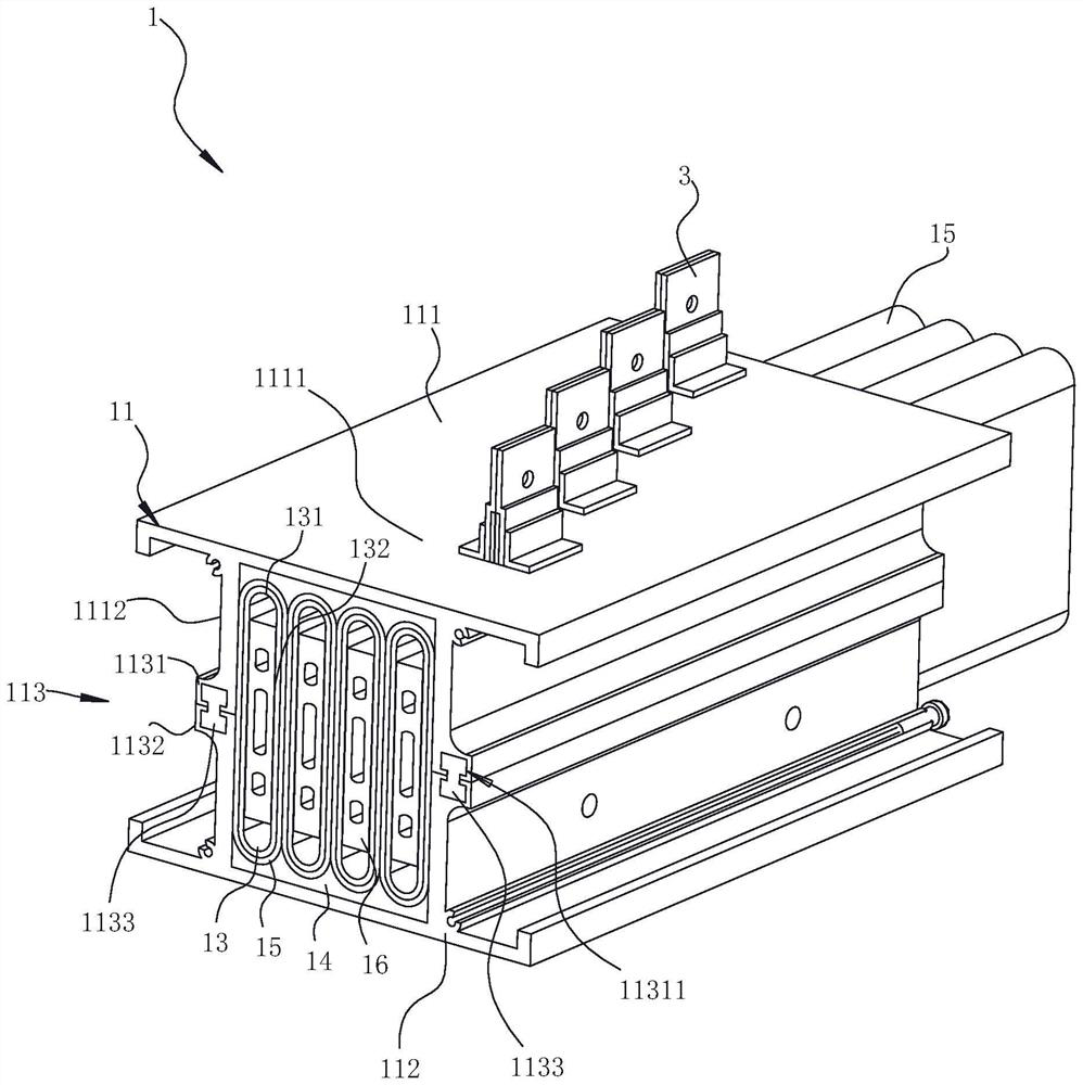
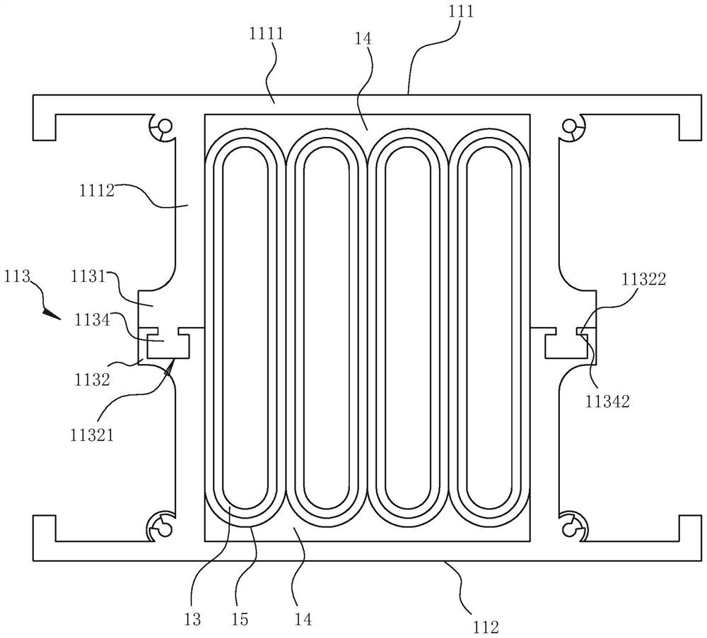
[0055] refer to figure 2 , the busbar 1 includes a shell 11, a conductive busbar and a filler 14, and the conductive busbar includes a plurality of tubular conductors 13 arranged in parallel. The housing 11 is an assembled housing 11, and the housing 11 includes two half-shells, namely a first half-shell 111 and a second half-shell 112, and the first half-shell 111 and the second half-shell 112 are through a lo...

Embodiment 2

[0071] A production process for a bus duct includes: first, selecting a copper plate and bending it into a tubular shape, welding both sides of the copper plate to make a tubular conductor 13; then extruding the tubular conductor 13 to form a flat tubular conductor 13, and then placing the tubular conductor 13 on the tubular conductor 13 is punched, an insulating film 15 is wound around the outer peripheral wall of the tubular conductor 13, and then the busbar is assembled. During assembly, the filler 14 is first laid on the inner surface of the bottom plate 1111 of the first half-shell 111 , and then a plurality of tubular conductors 13 wound with insulating films 15 are placed side by side in the first half-shell 111 . Another filling piece 14 is laid at the outer end of the second half-shell 112 , and then the second half-shell 112 is locked and connected with the first half-shell 111 .

[0072] The locking connection between the second half-shell 112 and the first half-she...


PUM


Abstract

The invention relates to a bus duct power distribution system and a bus duct production process, the bus duct power distribution system comprises a bus duct, the bus duct comprises a shell and a conductive busbar arranged in the shell, the conductive busbar comprises a plurality of tubular conductors arranged in parallel, and the tubular conductors are provided with plugging holes used for being connected with external power connection equipment. The periphery of the tubular conductor is coated with an insulating film, and a filling piece filled between the conductive busbar and the inner wall of the shell is also arranged in the shell. The bus duct can improve the heat dissipation effect of the conductor in the bus duct, and is suitable for low-voltage power distribution equipment.

Description

technical field [0001] The application belongs to the technical field of low-voltage power distribution, and in particular, relates to a busbar trunking power distribution system and a busbar trunking production process. Background technique [0002] With the emergence of modern engineering facilities and equipment, the power consumption of all walks of life has increased rapidly, especially the emergence of many high-rise buildings and large workshops, making the traditional cables as transmission conductors in the high-current transmission system can no longer meet the requirements. . At the same time, the bus duct emerges as a new type of distribution wire. The bus duct power distribution system is a power distribution device that transmits current efficiently. It is especially suitable for economical and reasonable wiring in increasingly tall buildings and large-scale factories. needs, and has great advantages in the transmission of large currents. [0003] The bus duc...

Claims


Application Information

Patent Timeline
IPC IPC(8): H02G5/06H02G5/10
CPCH02G5/06H02G5/10
Inventor 安查浩龚灏泽沈谊
Owner 深圳市爱得威母线制造有限公司
Why Eureka
Try Eureka