Power-outputting battery pack

A power output, power battery technology, applied in battery pack components, batteries, secondary batteries, etc., can solve the problems of high ambient temperature requirements, weak cooling effect, reliability and safety impact, etc., to achieve cooling effect. Significant, strong cooling effect, good cooling effect

Inactive Publication Date: 2018-10-16
高勇
View PDF0 Cites 0 Cited by
  • Summary
  • Abstract
  • Description
  • Claims
  • Application Information

AI Technical Summary

Problems solved by technology

At present, the commonly used power battery system is lithium-ion battery, which has the advantages of high energy density, excellent power output characteristics and long life, but it has high requirements on the temperature of the surrounding environment, and it will be used if the temperature is too high or too low Reliability and security have a greater impact
In the prior art, there is a design for cooling the power battery, but the cooling effect is weak, and it is difficult to meet the existing use requirements

Method used


Image

  • Power-outputting battery pack
  • Power-outputting battery pack

Examples


Embodiment 1

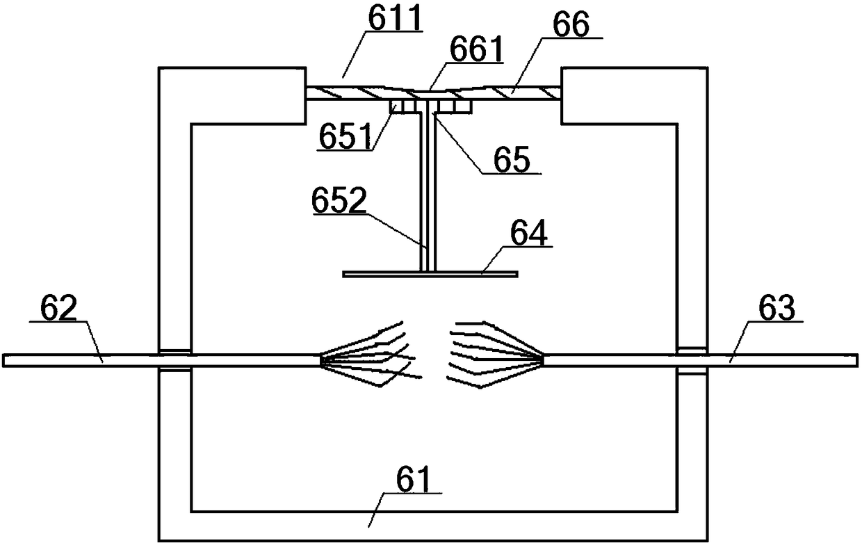
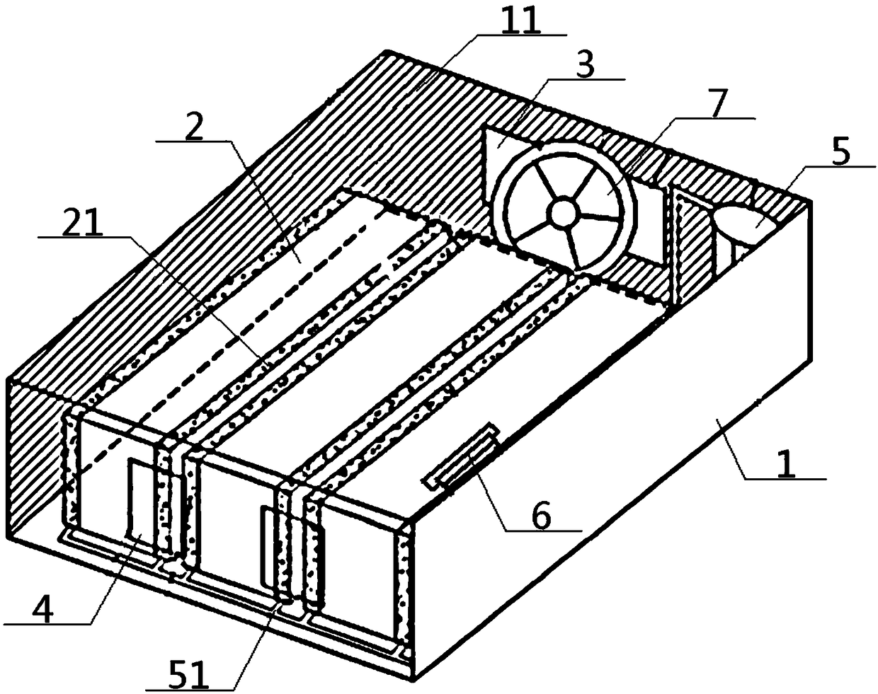
[0032] A power output battery pack, including a battery box 1, a power battery 2 and a cooling device, the power battery 2 is located in the middle of the battery box 1, and a cooling device is provided on the battery box 1; the cooling device includes a water cooling system With the air-cooled system, the air-cooled system includes a ventilation fan 7 and a temperature controller 6, and the ventilation fan 7 is connected to the power supply through the temperature controller 6; the temperature controller 6 includes a metal shell 61, an input power cord 62, Output power line 63, energizing sheet 64, insulating column 65 and bar-shaped temperature sensing sheet 66, one end of the input power line 62 is connected with the ventilation fan 7, and the other end of the input power line 62 passes through the left side of the metal casing 61 The wall extends to the inside of the metal casing 61, and one end of the output power line 63 is connected to the power supply, and the other end...

Embodiment 2

[0034] Basic content is the same as embodiment 1, the difference is:

[0035] The side wall of the battery box 1 is provided with an air inlet 3 at the position on the back of the ventilation fan 7, and the side wall of the battery box 1 is provided with an air outlet 4 at a position facing the ventilation fan 7, and the air inlet 3, the air outlet 4 facing the setting. A plurality of cooling fins 21 are uniformly arranged on the top of the power battery 2 , and adjacent cooling fins 21 are arranged parallel to each other. The side wall and the bottom wall of the battery box 1 are covered with a heat insulation and noise reduction protective layer 11 , and the heat insulation and noise reduction protection layer 11 is connected to the battery box 1 by bonding.

Embodiment 3

[0037] Basic content is the same as embodiment 1, the difference is:

[0038] The water cooling system includes a water pump 5 and a water flow circuit 51 , the water pump 5 communicates with one end of the water flow circuit 51 , and the other end of the water flow circuit 51 meanders through the bottom of the power battery 2 and then communicates with the water pump 5 . The meandering manner of the water flow circuit 51 is a back shape, a serpentine shape or a zigzag shape.


PUM


Abstract

The invention provides a power-outputting battery pack. The power-outputting battery pack comprises a battery box, a power battery and a cooling device, wherein the power battery is located at the central part of the battery box; the cooling device comprises a water cooling system and an air cooling system; the air cooling system comprises the ventilation fan and a temperature controller, and theventilation fan is connected with a power source via the temperature controller; the water cooling system comprises a water pump and a water flow loop, the water pump communicates with one end of thewater flow loop, and the other end of the water flow loop passes through the bottom of the power battery in a zigzag way and then communicates with the water pump; the top of the power battery is evenly provided with a plurality of heat sinks; and the side walls and the bottom wall of the battery box are covered with heat-insulating noise-reducing protection layers. With such a design, the power-outputting battery pack of the invention not only has strong cooling effect, but also has high automation degree.

Description

technical field [0001] The invention relates to a power battery device, in particular to a power output battery pack, which is particularly suitable for enhancing the cooling effect to ensure the constant temperature of the surrounding environment of the power battery. Background technique [0002] With the rapid development of electric vehicles, the power battery system, as the core component that directly affects the working performance of electric vehicles, has higher and higher performance requirements. At present, the commonly used power battery system is lithium-ion battery, which has the advantages of high energy density, excellent power output characteristics and long life, but it has high requirements on the temperature of the surrounding environment, and it will be used if the temperature is too high or too low Reliability and security have a greater impact. In the prior art, there is a design for cooling the power battery, but the cooling effect is weak, and it i...

Claims


Application Information

Patent Timeline
IPC IPC(8): H01M10/613H01M10/625H01M10/635H01M10/6551H01M10/6563H01M10/6568H01M10/658H01M2/10H01M50/204H01M50/24
CPCH01M10/613H01M10/625H01M10/635H01M10/6551H01M10/6563H01M10/6568H01M10/658H01M2220/20H01M50/24H01M50/20Y02E60/10
Inventor 高勇
Owner 高勇
Why Eureka
Try Eureka