
Motor rotor

A motor rotor and rotor technology, applied in asynchronous induction motors, electrical components, electromechanical devices, etc., can solve the problems of reduced heat dissipation area, increased rotor inertia, and increased materials, so as to improve starting performance, increase heat dissipation area, Effect of reducing rotor weight

Inactive Publication Date: 2012-07-18
MIDEA GRP CO LTD
View PDF3 Cites 14 Cited by
  • Summary
  • Abstract
  • Description
  • Claims
  • Application Information

AI Technical Summary

Problems solved by technology

[0002] The rotor of the traditional fan single-phase AC capacitor motor, one is to cast blades on the cast aluminum end rings at both ends of the squirrel cage-shaped rotor core. When the motor is running, the rotor drives the blades to stir the air to dissipate the heat of the motor; Heat dissipation device, there are problems such as easy deformation of blades during transportation
The other is to use the shaft sleeve with fan blades to fit tightly at both ends of the squirrel-cage rotor, so that the shaft sleeve is in contact with the rotor surface, the heat dissipation area is reduced, and the heat dissipation effect of the cross-flow wind generated is limited.
The above traditional motor heat dissipation methods all increase the cost of the motor. At the same time, the increase of materials increases the inertia of the rotor and the starting effect is poor.

Method used


Image

  • Motor rotor
  • Motor rotor
  • Motor rotor

Examples


Embodiment Construction

[0015] The present invention will be further described in detail below in conjunction with the accompanying drawings and embodiments.

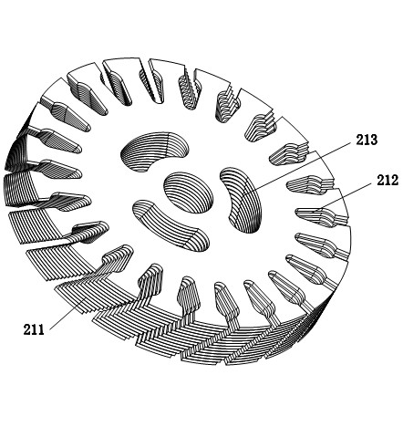
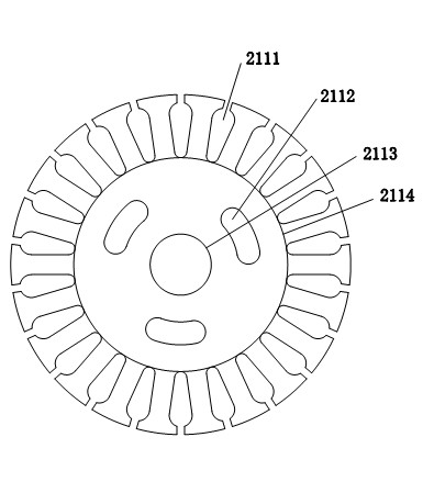
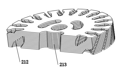
[0016] Such as Figures 1 to 5 As shown, a motor rotor includes a rotor shaft 1 and a squirrel cage-shaped rotor 2, wherein the rotor 2 is tightly sleeved on the rotor shaft 1, and the rotor 2 includes an aluminum-injected end ring 22 and an aluminum-injected end ring 22 In the rotor core 21, the rotor core 21 is formed by laminating several rotor punches 211, and several rotor punch slots 2111 are opened on the rotor punch 211, and several rotor punches 211 are stacked Together, the rotor core slot 212 is formed. The rotor core slot 212 runs through the rotor core 21. The aluminum injection end ring 22 is connected by the aluminum filled in the rotor core slot 212 and the aluminum distributed at the end of the rotor core 21. One, the feature of the present invention is that there are several evenly distributed through holes 2112 on the rotor...


PUM


Abstract

The invention relates to a motor rotor, which comprises a rotor shaft and a rotor in a rat cage shape, wherein the rotor is tightly sleeved on the rotor shaft, the rotor comprises an aluminum injection end ring and a rotor iron core arranged in the aluminum injection end ring, the rotor iron core is formed by the overlap of a plurality of pieces of rotor punching sheets, a plurality of evenly distributed rotor punching sheet grooves are arranged on the rotor punching sheets, a rotor iron core groove is formed by the overlap of a plurality of rotor punching sheet grooves, the aluminum injection end ring is integrated into a whole through aluminum filled in the rotor punching sheet grooves and aluminum distributed at the end portion of the rotor iron core. The motor rotor is characterized in that a plurality of evenly distributed through holes are arranged on the rotor punching sheets, the through holes are distributed between the inner ring of the rotor punching sheets and the minimal inner diameter of the rotor punching sheet grooves, and the rotor through holes are formed by the overlap of the plurality of the through holes. The cooling effect is better and service life of enameled wires is greatly prolonged, as the axial direction of the air pressure produced by through holes themselves is in accordance with the axial direction of the air pressure produced by motor load, and simultaneously, the through holes enlarge cooling areas. In addition, the through holes on the rotor reduce the weight of the rotor and are helpful for improving motor starting performance, and the reduction of raw materials reduces motor cost.

Description

technical field [0001] The invention relates to a motor rotor, in particular to a household fan single-phase AC capacitor motor rotor. Background technique [0002] The rotor of the traditional fan single-phase AC capacitor motor, one is to cast blades on the cast aluminum end rings at both ends of the squirrel cage-shaped rotor core. When the motor is running, the rotor drives the blades to stir the air to dissipate the heat of the motor; The heat dissipation device has problems such as the blades are easily deformed during transportation. The other is to use a shaft sleeve with fan blades to be tightly sleeved at both ends of the squirrel-cage rotor, so that the shaft sleeve contacts the surface of the rotor, the heat dissipation area is reduced, and the heat dissipation effect of the cross-flow wind produced is limited. The above traditional motor heat dissipation methods all increase the cost of the motor, and at the same time, the increase of materials increases the i...

Claims


Application Information

Patent Timeline
IPC IPC(8): H02K17/08H02K1/24H02K1/32
Inventor 廖启国杜舜杰彭颖卿汪志刚黄坤河
Owner MIDEA GRP CO LTD
Learn More