
Air-cooled motor

Inactive Publication Date: 2008-01-24
SCORPION PRECISION IND HK
View PDF3 Cites 14 Cited by
  • Summary
  • Abstract
  • Description
  • Claims
  • Application Information

AI Technical Summary

Benefits of technology

[0009]An air-cooled motor is presented, which overcomes the problems noted above and has compact structure with a good cooling effect.
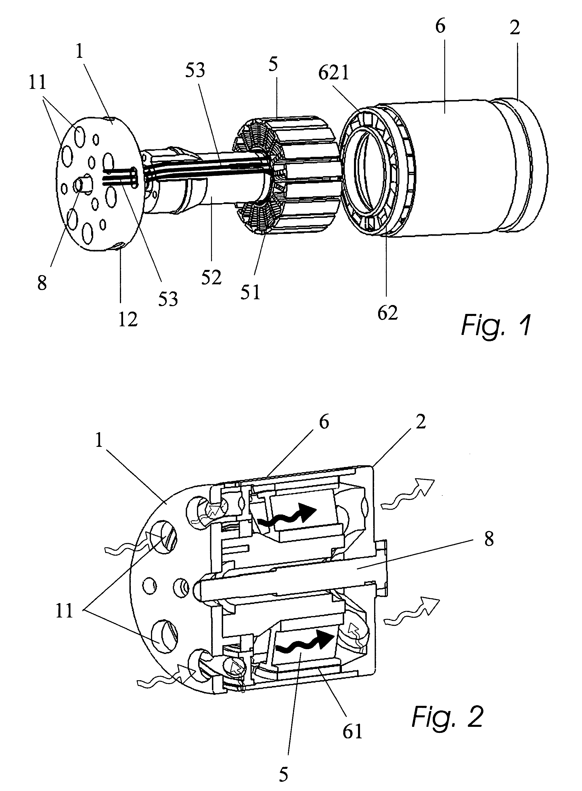
[0020]A main structural improvement is made to the motor according to the invention in that the front portion of the rotor is arranged with an air-inflow disk having one or more oblique air intake grooves. In the operational mode of the motor, the air-inflow disk is driven by the rotor to rotate at a high speed so that each of the air intake grooves forms a windward angle in its oblique direction relative to the rotation direction of the rotor. This design of windward angles enables the air intake grooves rotating at a high speed to forcedly bring cooling air flows into the interior of the motor of the invention in its operational state, thereby a forced cooling effect is achieved. Apart from this, the internal compact cooling arrangement allows the motor of the invention to be produced inexpensively and in a relatively small size. Consequently, it has a wide range of applications and good adaptability.
[0021]The air-cooled motor of the invention is also provided at the rear end of the rotor with an air-exhausting disk having one or more oblique air outlet grooves. Likewise, each of the air outlet grooves forms a windward angle in its oblique direction relative to the rotation direction of the rotor, which enables the air outlet grooves rotating at a high speed to forcedly take hot air flows out of the interior of the motor of the invention in its operational state. The combined effect of the air-inflow disk and the air-exhausting disk provides a higher cooling efficiency of the motor of the invention.

Problems solved by technology

When the motor is in its operation state, the coil generates heat after being electrically-coupled to cause a rise in temperature within the rotor, and friction between the rotor at high speed and the air is another main factor that leads to generation of heat within the motor, resulting in a further rise in the temperature of the motor.
This rise produces a thermal effect that greatly reduces the efficiency of the motor as well as shortens the service life of the motor.
However, this kind of motor suffers from relatively complicated structure and high manufacturing cost.
Due to an external arrangement of the electric fan, the dimension of this kind of motor is larger than an ordinary motor of the same power, resulting in limited applications thereof.
For this motor, the overall size of the cooling means is relatively large and the noise brought about by the electric fan is relatively high.
It can been seen from the above that motors with an internally-disposed cooling means or with an externally-disposed cooling means using either air or liquids as a cooling medium, or combination thereof, are commonly available in the art, but each of them has its own drawbacks.
Generally speaking, use of liquid produces a cooling effect better than that produced by air cooling because the liquid has a high efficient heat conductivity, but complicated and large structure is required for such a motor because consideration must be taken to the accompanying problems such as sealing of the liquid.
As a result, it is expensive to make a motor using liquid as a cooling medium.
Usually, cooling means intended for being externally disposed is simple in structure and inexpensive to manufacture, but causes the overall size of the motor to become large and its applications are therefore subject to limited circumstances.

Method used


Image

  • Air-cooled motor
  • Air-cooled motor
  • Air-cooled motor

Examples


Embodiment Construction

[0029]Referring now to the drawings wherein the showings are for purposes of illustrating preferred embodiments of the present invention only, and not for purposes of limiting the same.

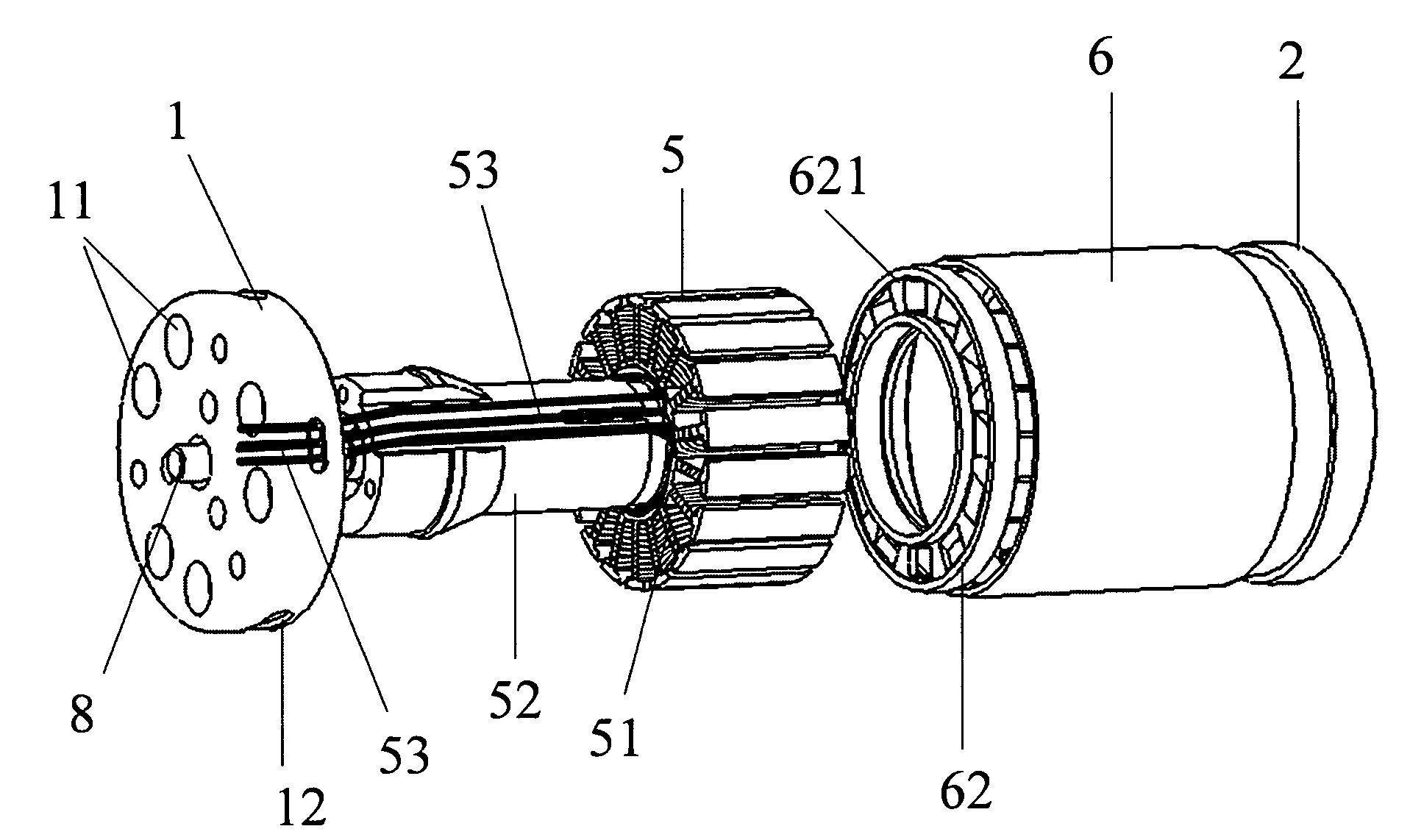
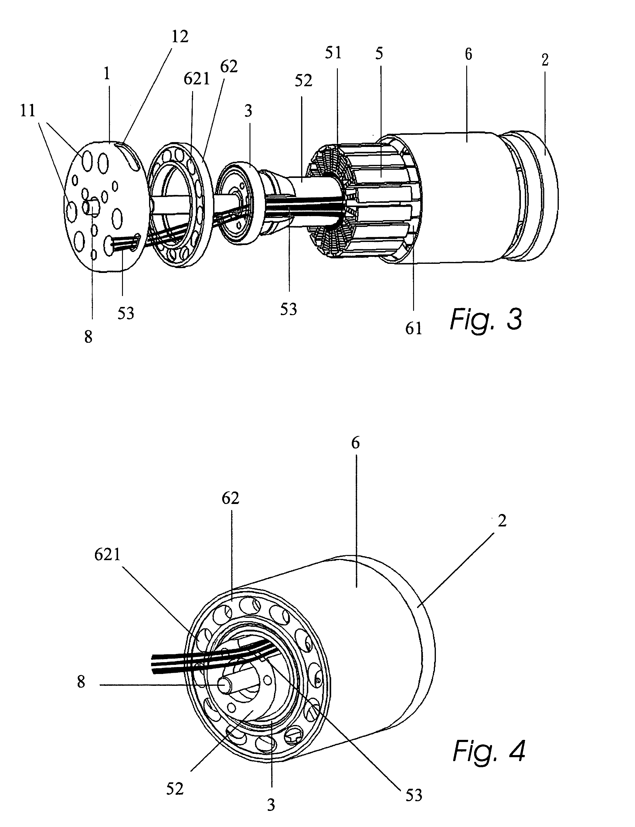
[0030]FIG. 1 illustrates an air-cooled motor consistent with a first preferred embodiment of the present invention. In this embodiment, the motor comprises a motor shaft 8, a stator 5 and a rotor 6 which are co-axially disposed with the motor shaft 8. The stator 5 has at its front side a front cover 1 on which wind tunnels 11 and a central hole are arranged. The motor shaft 8 passes through the central hole of the front cover 1 to be exposed to the outside of the motor. The stator 5 is constituted by a main body which is a coil 51 coupled to conductive wires 53. The conductive wires 53 are connected with an external power source for bringing energization to the coil 51 in the operational state of the motor. The motor shaft 8 is axially fitted with a fixed seat 52 for supporting the stator 5. The fixed...


PUM


Abstract

An air-cooled motor is disclosed, comprising a motor shaft, a stator and a rotor which are disposed co-axially, said motor shaft being fitted with a fixed seat for supporting said stator and being operatably connected with said rotor and rotatably connected with said stator, said stator having a coil coupled to conductive wires; further comprising a front cover disposed at the front side of said rotor and having wind channels, wherein a front end portion of said rotor in the proximity of said front cover is provided with an air-inflow disk which has one or more air intake grooves each passing obliquely therethrough to form a windward angle relative to the rotation direction of said rotor; and said motor further comprises an air-exhausting disk which has one or more air outlet grooves each passing obliquely therethrough to form a windward angle relative to the rotation direction of said rotor.

Description

FIELD OF THE INVENTION[0001]The present invention relates to the field of electrical machinery, and particularly to an electric motor with internally forced air cooling system.BACKGROUND OF THE INVENTION[0002]Most of commercially available motors, based on the principle of electromagnetic effect, structurally include a coil used as a stator and a metallic sleeve having magnets used as a rotor. When the motor is in its operation state, the coil generates heat after being electrically-coupled to cause a rise in temperature within the rotor, and friction between the rotor at high speed and the air is another main factor that leads to generation of heat within the motor, resulting in a further rise in the temperature of the motor. This rise produces a thermal effect that greatly reduces the efficiency of the motor as well as shortens the service life of the motor. Therefore, it has been continuously under investigation in the art to cool down the motor or lower the temperature of the mo...

Claims


Application Information

Patent Timeline
IPC IPC(8): B60S1/54
CPCH02K5/20H02K9/06H02K5/225H02K5/207
Inventor VAN GANSEN, GEORGES A.M.
Owner SCORPION PRECISION IND HK
Learn More