Bottle blowing machine control system and bottle blowing machine

A control system and blow molding machine technology, applied in the direction of comprehensive factory control, etc., can solve the problems of messy wiring, maintenance and line finding

Pending Publication Date: 2022-07-12
GUANGZHOU TECH LONG PACKAGING MACHINERY CO LTD
View PDF0 Cites 1 Cited by
  • Summary
  • Abstract
  • Description
  • Claims
  • Application Information

AI Technical Summary

Problems solved by technology

[0004] The embodiment of the present invention proposes a bottle blowing machine control system and a bottle blowing machine to

Method used


Image

  • Bottle blowing machine control system and bottle blowing machine
  • Bottle blowing machine control system and bottle blowing machine
  • Bottle blowing machine control system and bottle blowing machine

Examples


Embodiment 1

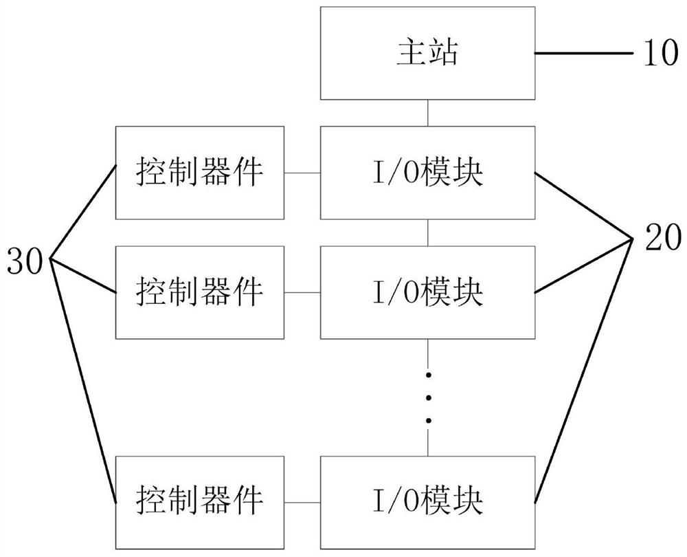
[0034] figure 1 This is a structural block diagram of a bottle blowing machine control system provided in Embodiment 1 of the present invention. The bottle blowing machine control system of this embodiment can be applied to a bottle blowing machine provided with multiple mold bases, which reduces the number of mold bases on the bottle blowing machine. On the basis of the connection with the master station, the process parameters of each mold base are controlled.

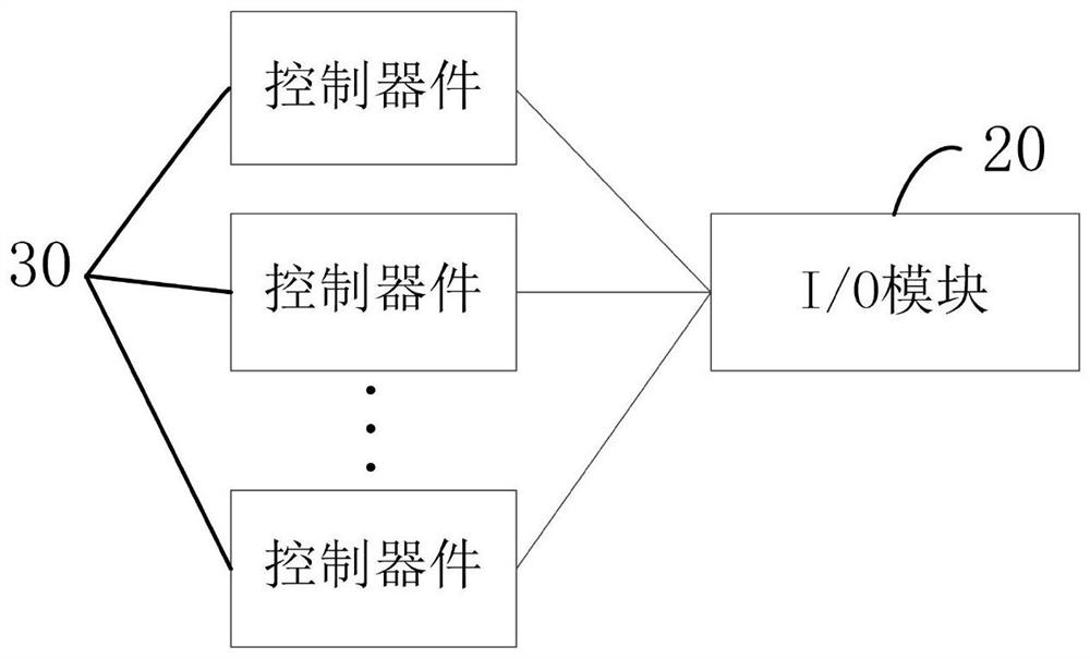
[0035] like figure 1 As shown, the bottle blowing machine control system of the embodiment of the present invention includes a master station 10, an I / O module 20 arranged on each mold base as a slave station, and on each mold base, the control device 30 is connected to the I / O The modules 20 are connected, and the I / O modules 20 on each mold frame are connected in sequence and then connected to the master station 10 .

[0036] The I / O modules 20 can include discrete, analog, and special modules of various types. T...

Embodiment 2

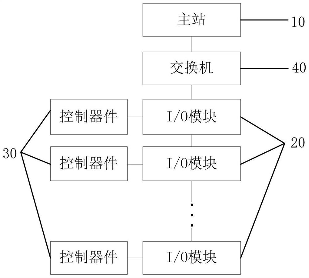
[0055] Figure 4 It is a schematic structural diagram of a bottle blowing machine provided in the second embodiment of the present invention. The bottle blowing machine is provided with at least one mold frame 50, and each mold frame 50 is provided with at least one control device 30. The bottle blowing machine also includes the first embodiment. The blow molding machine control system. The bottle blowing machine control system includes a master station 10 and an I / O module 20 arranged on each mold base 50 as a slave station. On each mold base 50, the control device 30 is connected to the I / O module 20, and each mold base 50 is connected to the I / O module 20. The I / O modules 20 on the 50 are connected in sequence and then connected to the master station 10. The master station 10 is used to communicate with the control device 30 on the mold base 50 through the I / O modules 20 on each mold base 50 to control the control device. 30 Perform the blowing action.

[0056] The bottle...


PUM


Abstract

The embodiment of the invention provides a bottle blowing machine control system and a bottle blowing machine, the bottle blowing machine control system comprises a master station and I/O modules arranged on each mold frame as slave stations, a control device on each mold frame is connected with the I/O modules, the I/O modules on the mold frames are sequentially connected and then connected with the master station, and the master station is connected with the master station. And the main station is used for communicating with the control device on the mold frame through the I/O module on each mold frame so as to control the control device to execute a bottle blowing action. The control device can be a set of a plurality of control switches or valves and the like, each mold frame is provided with one I/O module to connect all the control devices on the mold frame, and then the mold frame is uniformly connected with a main station through the I/O modules, so that the number of connecting lines between each mold frame and the main station is reduced, and the I/O modules are connected with the main station after being connected in sequence; and connecting lines between the mold frame and the main station are further reduced, and the problems that wiring is disordered, and great troubles are caused to line finding in later maintenance in a traditional scheme are solved.

Description

technical field [0001] The embodiments of the present invention relate to the technical field of safety control, and in particular, to a bottle blowing machine control system and a bottle blowing machine. Background technique [0002] The bottle blowing machine is a device for blowing and molding the preform. The existing rotary bottle blowing machine includes a gyratory main body and a plurality of mold bases arranged around the gyratory body. The production module valve, the main blowing pressure sensor, the tensile limit proximity switch, etc., and because the rotary blow molding machine is a high-speed rotating equipment, the control of the blowing process of each mold frame is relatively complicated. Therefore, automated production is adopted. The modular system is extremely important. [0003] The traditional solution is to install a small electric box on the top rotating disk. Due to the limited space of the rotating disk, the small electric box is equipped with PLC ...

Claims


Application Information

Patent Timeline
IPC IPC(8): B29C49/78
CPCB29C49/78Y02P90/02
Inventor 凌思思邓浩广
Owner GUANGZHOU TECH LONG PACKAGING MACHINERY CO LTD
Why Eureka
Try Eureka