Power supply device

a power supply device and power supply technology, applied in the direction of process and machine control, electronic components association, instruments, etc., can solve the problems of heat dissipation disadvantageous configuration of the transformer or the choke coil between the circuit board and the semiconductor components, etc., to reduce the distance between the circuit board and any of the electronic components, reduce the length of the wire between the circuit board and the electronic components, and reduce the size of the power supply apparatus

Active Publication Date: 2018-12-20
DENSO CORP
View PDF0 Cites 4 Cited by
  • Summary
  • Abstract
  • Description
  • Claims
  • Application Information

AI Technical Summary

Benefits of technology

[0014]The power supply device is provided with the first stacked body and the second stacked body each of which is formed from the two electrical components which include, the transformer, the primary semiconductor component, the secondary semiconductor component, and the choke coil. According to the configuration, a disposed space of the electrical components, viewed in the normal direction of the board may be decreased, thus, downsizing of the power supply apparatus also achieved.
[0015]In addition, the circuit board is interposed between the electronic components in the pair forming the first stacked body, and between the electronic components in the other pair forming the second stacked body. Therefore, a distance between the circuit board and any of the electronic components can be reduced and lengths of wires between the circuit board and the electronic components may also be reduced. Furthermore, noise which is caused by the connecting wires may also be reduced as a result.
[0016]Furthermore, since the plurality of electronic components are dispersed on both sides of the circuit board, and heat from the electronic components is easily dissipated. In other words, heat dissipation efficiency of the power supply device can be enhanced.
[0017]As described above, according to the above-described mode a power supply device in which downsizing thereof is achieved, in addition to noise reduction, and an improved heat dissipation efficiency may also be provided.

Problems solved by technology

In addition, the configuration in which the transformer or the choke coil is interposed between the circuit board and the semiconductor components is likely to be disadvantageous in terms of heat dissipation of the transformer or the choke coil.

Method used


Image

  • Power supply device
  • Power supply device
  • Power supply device

Examples


first embodiment

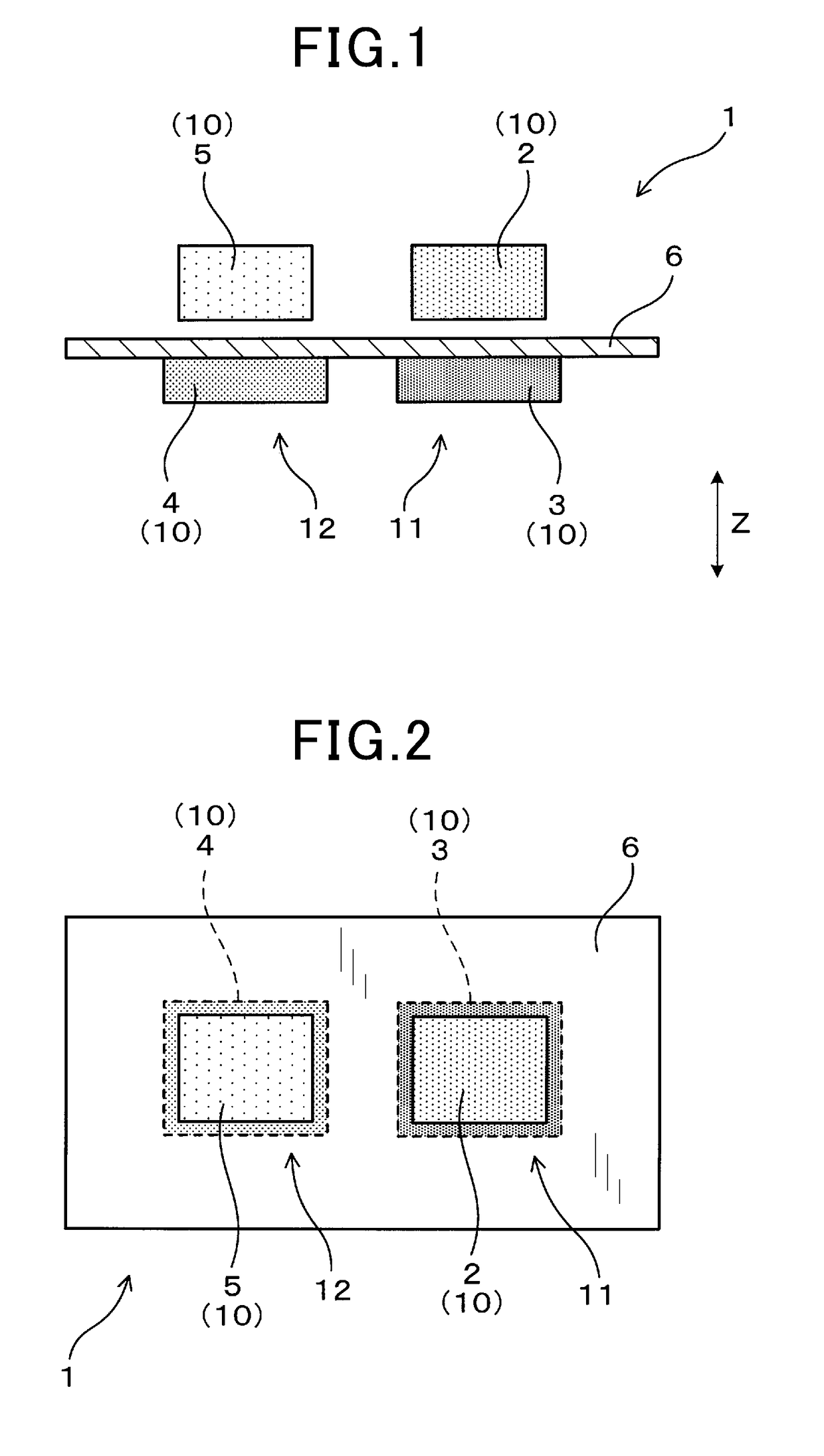
[0043]Embodiments of a power supply device will now be described with reference to FIGS. 1 to 3.

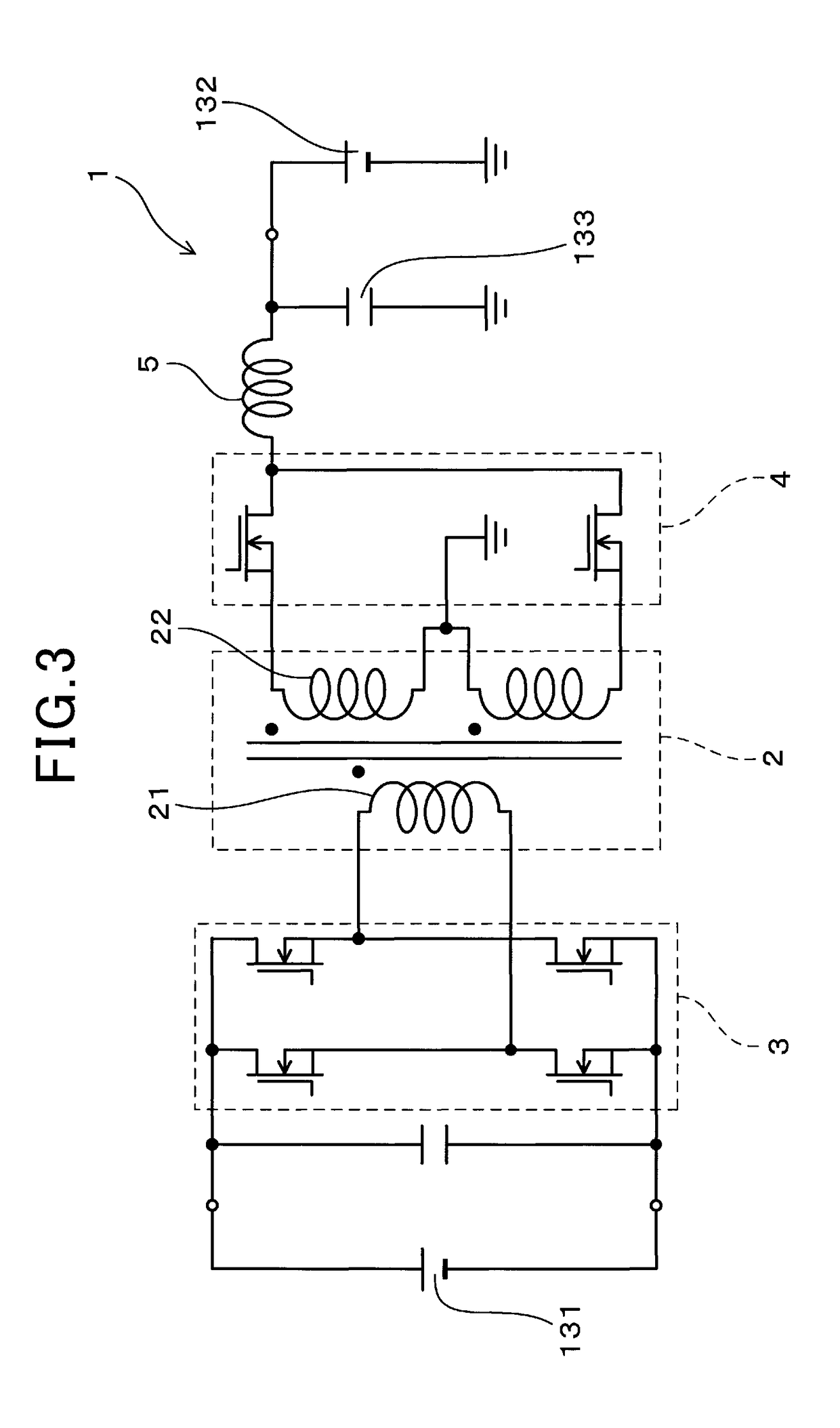
[0044]As illustrated in FIGS. 1 and 2, a power supply device 1 includes a transformer 2, a primary semiconductor component 3, a secondary semiconductor component 4, a choke coil 5, and a circuit board 6.

[0045]As shown in FIG. 3, the transformer 2 includes a primary coil 21 and a secondary coil 22. The primary semiconductor component 3 forms a primary circuit which is connected to the primary coil 21 of the transformer 2. The secondary semiconductor component 4 forms a secondary circuit which is connected to the secondary coil 22 of the transformer 2. The choke coil 5 forms the secondary circuit in collaboration with the secondary semiconductor component 4. A control circuit is formed on the circuit board 6.

[0046]As shown in FIGS. 1 and 2, pairs of electronic components 10 are stacked in the normal direction Z of the board, each of the pairs forming the respective first stacked body 11 and...

second embodiment

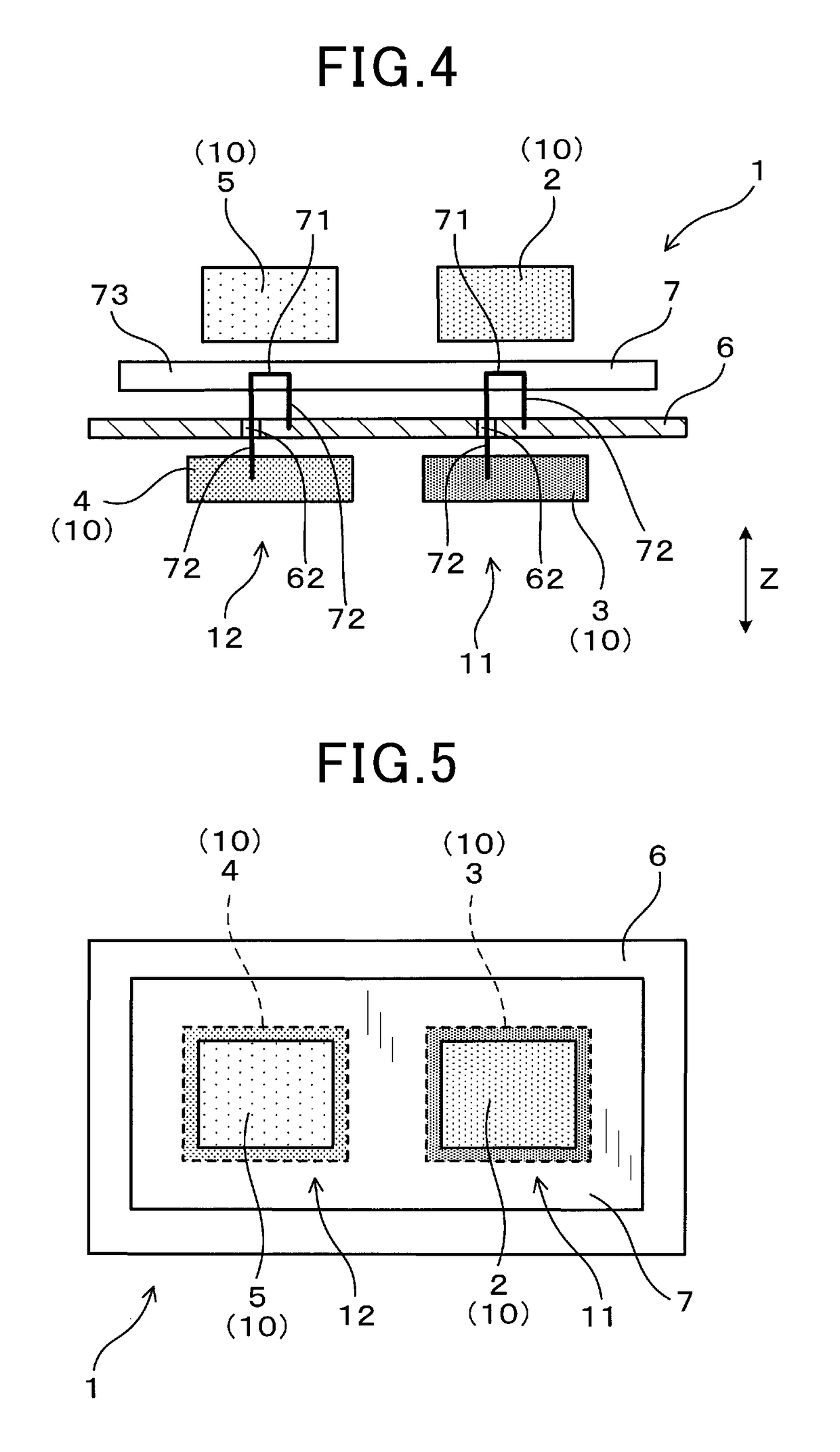
[0064]As illustrated in FIGS. 4 and 5, the power supply device 1 according to a second embodiment further includes a connecting member 7.

[0065]The connecting member 7 electrically connects the plurality of electronic components 10 to each other, or the electronic components 10 and the circuit board 6 to each other. The connecting member 7 is provided between the pair of the electronic components 10 which forms the first stacked body 11, and between the other pair of the electronic components 10 which forms the second stacked body 12. In the present embodiment, the connecting member 7 is interposed between the transformer 2 and the primary semiconductor component 3, and between the choke coil 5 and the secondary semiconductor component 4. In addition, the connecting member 7 is arranged on the upper-side of the circuit board 6. Note that, the connecting member 7 may also be arranged on the lower-side of the circuit board 6.

[0066]The connecting member 7 includes conductive body portio...

third embodiment

[0074]According to a third embodiment, at least one of the transformer 2 and the choke coil 5, is electrically connected to the circuit board 6 via the connection terminal portions 72 and the conductive body portions 71.

[0075]More specifically, both the transformer 2 and the choke coil 5, and the circuit board 6 are electrically connected to each other via the connection terminal portions 72 and the conductive body portions 71 of the connecting member 7.

[0076]As shown in the circuit diagram of FIG. 7, a pair of terminals of the primary coil 21 of the transformer 2 are connected to the circuit board 6 via the connecting member 7. In addition, the primary semiconductor component 3 which is mounted onto the circuit board 6 is connected to conductive wires formed on the circuit board 6. Therefore, the primary coil 21 is electrically connected to the primary semiconductor component 3 via the connecting member 7 and the circuit board 6.

[0077]Specifically, the conductive wires formed on th...


PUM

PropertyMeasurementUnit
conductiveaaaaaaaaaa
electric componentsaaaaaaaaaa
lengthsaaaaaaaaaa

Abstract

A power supply device includes a transformer, a primary semiconductor component, a secondary semiconductor component, a choke coil and a circuit board. Electronic components which include the transformer, the primary semiconductor component, the secondary semiconductor component, and the choke coil, are stacked in pairs, in a normal direction of a board. One pair forms a first stacked body and another pair to forms a second stacked body. A circuit board is interposed between the one pair of electronic components which forms the first stacked body, and also between the other pair of electronic components which forms the second stacked body.

Description

CROSS REFERENCE TO RELATED APPLICATIONS[0001]This application claims the benefit of priority of Japanese Patent Application No. 2015-247539 filed on Dec. 18, 2015, the entire contents of which are incorporated herein by reference.TECHNICAL FIELD[0002]The present disclosure relates to a power supply device.BACKGROUND ART[0003]Power supply devices such as a DC-DC converter and a charging device provided therewith have been used, for example, in hybrid cars and electric cars. Such power supply devices include a transformer, a choke coil, a primary semiconductor component, and a secondary semiconductor component. Patent Literature 1 discloses a power supply device in which two stacking bodies are formed by stacking the plurality of electronic components respectively into pairs. With this, downsizing and noise reduction of the power supply device are achieved.CITATION LISTPatent Literature[0004][PTL 1] JP 2015-47058 ASUMMARY OF THE INVENTION[0005]A power supply device in general includes...

Claims


Application Information

Patent Timeline
Patent Type & Authority Applications(United States)
IPC IPC(8): H02M1/44H02M3/335H05K1/18H05K1/11H01F27/28H01F27/24
CPCH02M3/3382H02M3/33507H02M7/003H02M1/44H05K1/184H01F27/24H05K1/115H01F27/28H02M3/33576H02M3/33584H02M3/003H02M3/28
Inventor ANDO, KEIICHIHANDA, YUICHINAKAMURA, KIMIKAZUKOKETSU, KAORUYAMADA, YUKIIYASU, SEIJIKURAUCHI, SHUJI
Owner DENSO CORP
Why Eureka
Try Eureka