Bobbin, motor, and method of winding magnet wire

a technology of winding magnet wire and bobbin, which is applied in the direction of windings, magnetic circuit rotating parts, magnetic circuit shape/form/construction, etc., can solve the problems of reducing the reliability of protection, limiting the approach, etc., and achieves the effect of increasing the winding space of a magnet, increasing the diameter of the flange, and increasing the motor dimension

Inactive Publication Date: 2005-02-24
MINEBEA CO LTD
View PDF6 Cites 16 Cited by
  • Summary
  • Abstract
  • Description
  • Claims
  • Application Information

AI Technical Summary

Benefits of technology

Since the bobbin included in the motor described as above has an increased winding space for a magnet compared to a conventional bobbin which has a constant body section diameter equal to the lateral body section diameter all the way between two flanges, the number of turns of the magnet wire around the bobbin can be increased without increasing the diameter of the flanges thus without increasing the motor dimension. If the number of turns of the magnet wire is set to remain unchanged, then the diameter of

Problems solved by technology

This approach, however, is hitting a limit for the reason of angle resolution, and also torque characteristic.
This approach, howe

Method used


Image

  • Bobbin, motor, and method of winding magnet wire
  • Bobbin, motor, and method of winding magnet wire
  • Bobbin, motor, and method of winding magnet wire

Examples


first embodiment

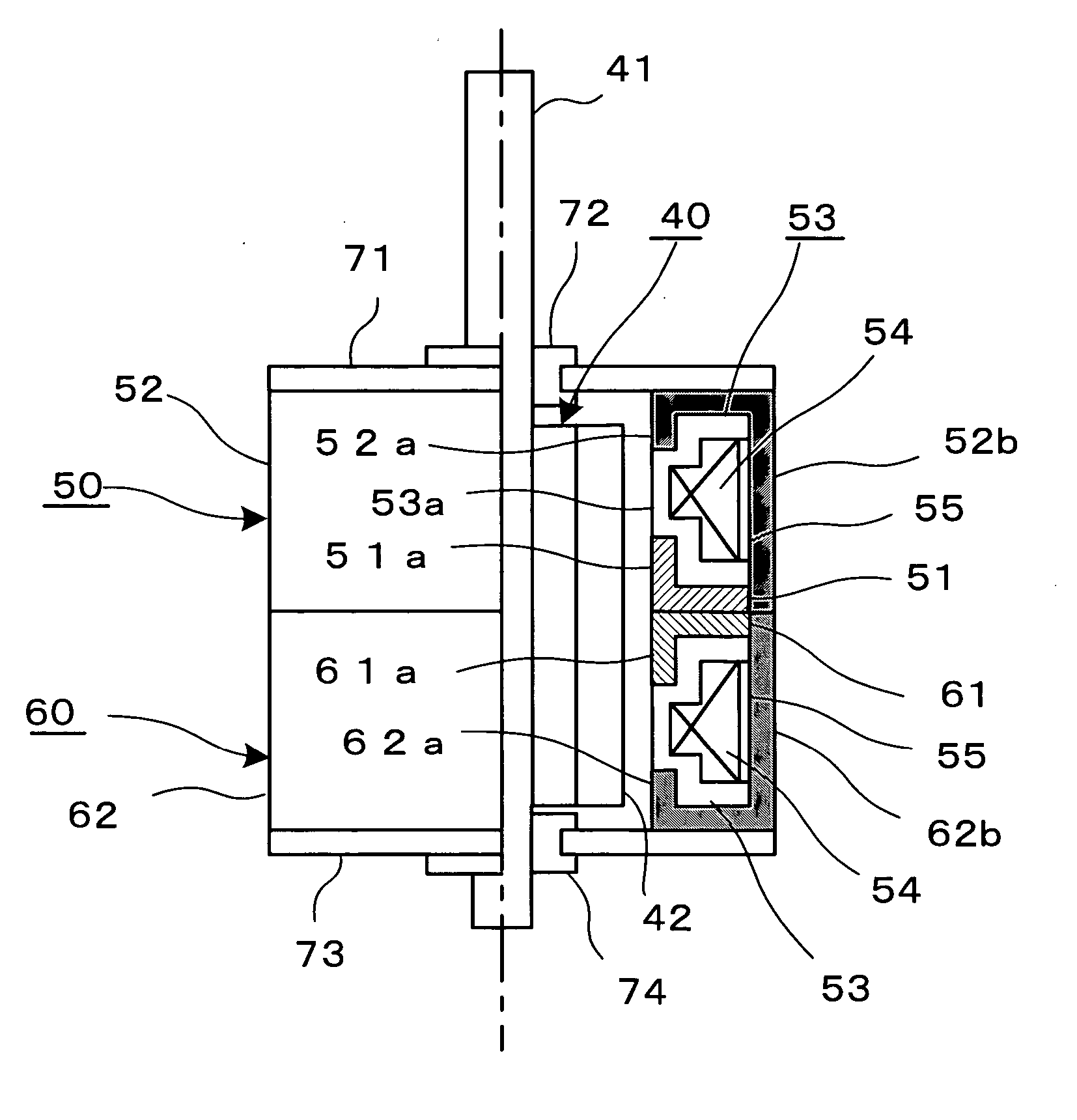
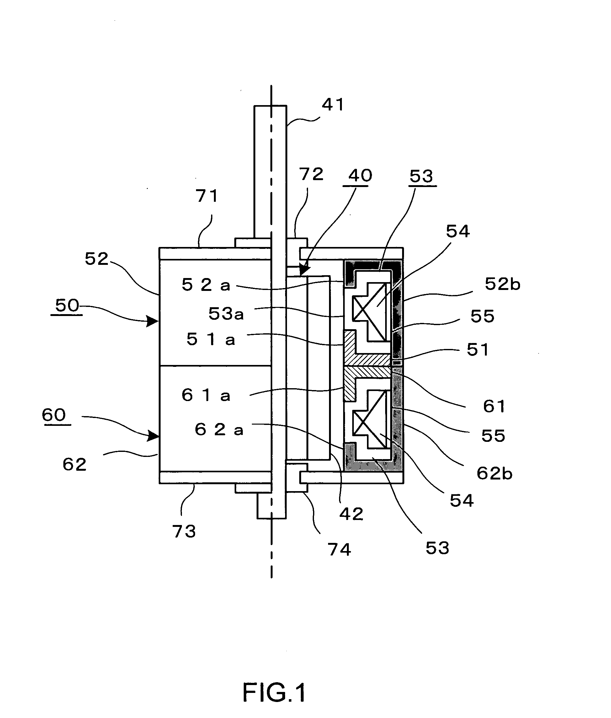
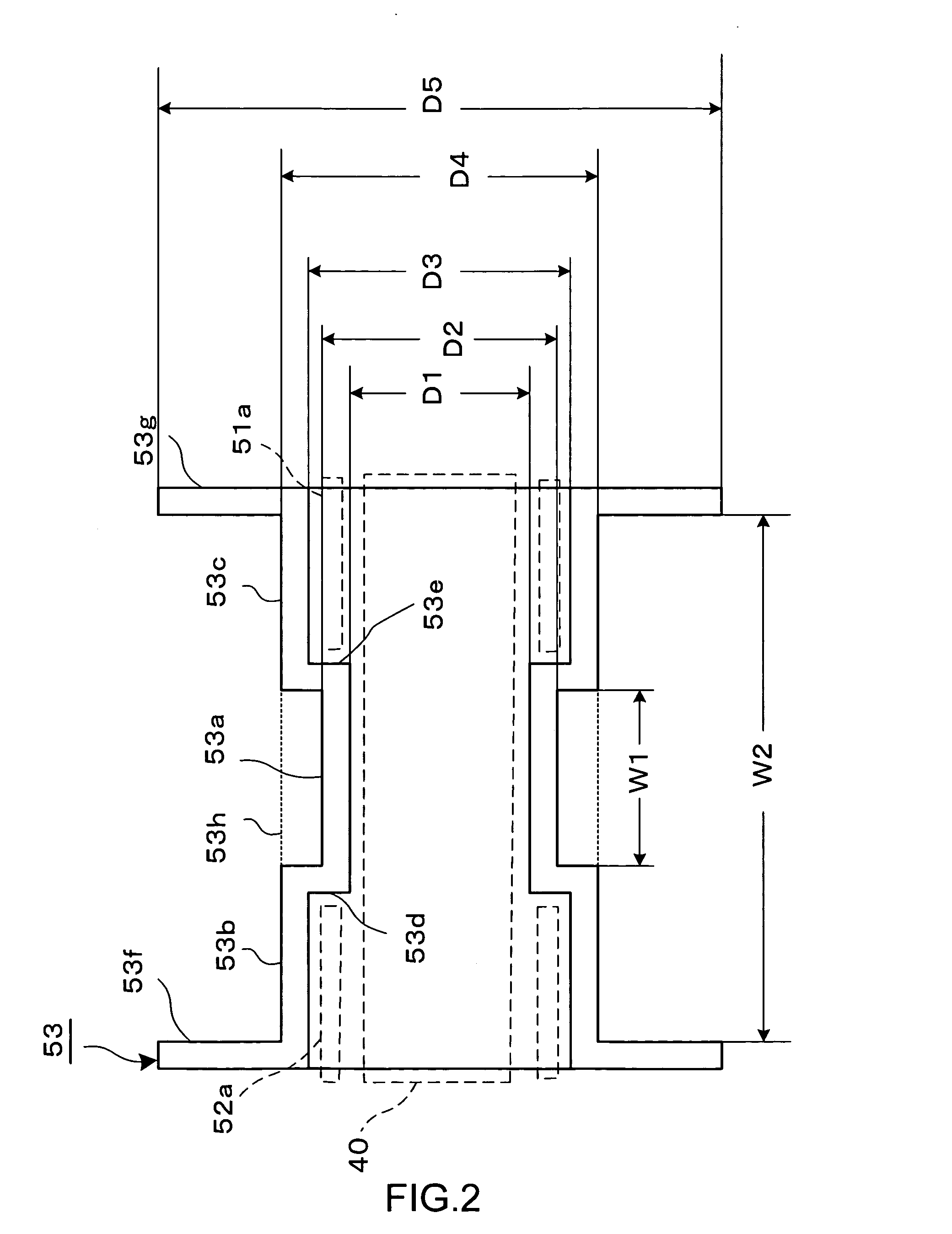
the present invention will be described with reference to FIGS. 1 and 2.

A stepping motor shown in FIG. 1 is capable of two-phase driving, and comprises a rotor assembly 40, and two stator units 50 and 60.

The rotor assembly 10 is shaped substantially cylindrical, and is composed of a permanent magnet with a plurality of magnetic poles 42, and a rotary shaft 41 passing through the center of the magnet.

The stator unit 50 includes first and second yokes 51 and 52 arranged to oppose each other, and a bobbin 53. The bobbin 53 has a magnet wire 54 wound therearound, and an insulator 55 is disposed around the magnet wire 54 wound. The bobbin 53 is sandwiched between the first and second yokes 51 and 52.

The first yoke 51 is punched out of a soft-magnetic plate into a disk having at its center a circular opening for letting the rotor assembly 40 through. A plurality of pole teeth 51a are formed along an inner circumference of the first yoke 51 defined by the circular opening and are be...

second embodiment

the present invention will be described with reference to FIG. 3.

A bobbin 81 shown in FIG. 3 is formed of synthetic resin, and comprises a middle body section 81a shaped hollow-cylindrical, and two lateral body sections 81b and 81c shaped hollow-cylindrical and having a larger diameter than the middle body section 81a. One end of the middle body section 81a is connected to one end of the lateral body section 81b via a joining section 81d with a gradual change in diametrical dimension thus not forming a step configuration, and the other end of the middle body section 81a is connected to one end of the lateral body section 81c via a joining section 81e with a gradual change in diametrical dimension thus not forming a step configuration. The hollows of the middle body section 81a, and the lateral body sections 81b and 81c are set coaxial to one another. A flange 81f is formed at the distal end of the lateral body section 81b so as to radially extend outward, and a flange 81g is formed...


PUM


Abstract

A bobbin comprises three hollow-cylindrical sections, specifically a middle body section, and two lateral body sections. The middle body section has its diameter diminished compared to the two lateral body sections thus forming an annular recess which allows a magnet wire to be wound with an additional number of turns around the bobbin without increasing a motor size. With this bobbin structure, when the number of turns of a magnet wire is set to remain unchanged, the diameter of flanges of the bobbin can be reduced resulting in a downsized motor.

Description

BACKGROUND OF THE INVENTION 1. Field of the Invention The present invention relates to a bobbin around which a magnet wire is wound, to a motor in which the bobbin is incorporated, and further to a method of winding a magnet wire around the bobbin. 2. Description of the Related Art FIG. 5 is a partly cross-sectioned axial view of a conventional stepping motor. The conventional stepping motor comprises a rotor assembly 10, and a stator assembly composed of two stator units 20 and 30. The rotor assembly 10 is shaped substantially cylindrical, and composed of a permanent magnet with a plurality of magnetic poles 11 arranged on its outer circumference, and a rotary shaft 12 passing through the center of the magnet. The stator units 20 and 30 have respective center openings and are attached to each other coaxially, and the rotor assembly 10 is rotatably housed in the center openings. The stator unit 20 includes yoke members 21 and 22 arranged to oppose each other, and a bobbin 24 ha...

Claims


Application Information

Patent Timeline
IPC IPC(8): H01F5/02H01F41/06H02K3/18H02K3/46H02K15/04H02K21/14H02K37/04H02K37/14
CPCH01F5/02H01F41/0633H02K37/14H02K15/0435H02K21/145H02K3/18H01F41/082
Inventor SUZUKI, YUZURU
Owner MINEBEA CO LTD
Why Eureka
Try Eureka